
Effect of counter-electrode-area-to-working-electrode area on hydrogen uptake and mechanical behavior under electrochemical charging

Copyright © The Korean Society of Marine Engineering
This is an Open Access article distributed under the terms of the Creative Commons Attribution Non-Commercial License (http://creativecommons.org/licenses/by-nc/3.0), which permits unrestricted non-commercial use, distribution, and reproduction in any medium, provided the original work is properly cited.
Abstract
Electrochemical hydrogen charging is widely used to evaluate hydrogen embrittlement in metallic materials. However, ISO 16573 mainly specifies current density, charging time, and electrolyte conditions, while geometric factors such as electrode configuration are not sufficiently addressed. This study investigated the effect of the working-electrode-to-counter-electrode (WE:CE) area ratio on the hydrogen uptake of STS 304L austenitic stainless steel. The WE:CE ratios were set to 1:1, 1:2, 1:4, and 1:10 using a platinum-mesh counter electrode, and the hydrogen content was measured by ONH analysis at two current densities. The hydrogen content varied with the area ratio: it was relatively high at 1:1, decreased at 1:2 and 1:4, and increased again at 1:10, which may be associated with changes in counter-electrode current density, polarization, and cell current distribution that altered the charging conditions at the working-electrode surface. Slow strain rate tensile (SSRT) tests showed no notable differences in mechanical properties among the conditions, suggesting that the differences in total hydrogen content did not translate into measurable mechanical degradation. These results indicate that the WE:CE area ratio is a geometric variable — not specified in ISO 16573 — that can influence hydrogen uptake and should therefore be controlled and reported to improve the reproducibility of electrochemical hydrogen-charging tests.
Keywords:
Hydrogen embrittlement, Electrochemical hydrogen charging, WE area ratio, STS 304L, Slow strain rate tensile test1. Introduction
Extensive research has been conducted on eco-friendly energy technologies to replace conventional fossil fuels. In particular, hydrogen has attracted considerable attention as a next-generation energy source, owing to its high gravimetric energy density and its role as a carbon-free energy carrier that emits no carbon dioxide during use [1][2]. However, because of its small atomic size, hydrogen can readily penetrate into metals, which may lead to hydrogen embrittlement, a phenomenon characterized by the degradation of ductility and strength in metallic materials. Since hydrogen embrittlement can cause unexpected cracking and failure of structures, it is essential to quantitatively evaluate the hydrogen embrittlement behavior of metallic materials used in hydrogen environments [3].
Various hydrogen charging methods have been employed to evaluate the hydrogen embrittlement characteristics of metallic materials, among which gaseous hydrogen charging and electrochemical hydrogen charging are the most representative [4].
Gaseous hydrogen charging offers the advantage of relatively directly simulating an actual hydrogen service environment; however, it involves risks of ignition, explosion, and leakage associated with the use of high-pressure hydrogen, and requires specialized high-pressure equipment and safety facilities [5]. In contrast, electrochemical hydrogen charging has been widely employed to evaluate the hydrogen embrittlement behavior of metallic materials at the laboratory scale, owing to its relatively simple experimental setup and ease of controlling test conditions. Furthermore, since the amount of hydrogen generated in a laboratory-scale electrochemical cell is limited, tests can be conducted relatively safely compared with gaseous hydrogen charging, provided that adequate ventilation and safety measures are ensured [6][7].
Electrochemical hydrogen charging tests are generally performed in accordance with ISO 16573, which specifies major test conditions such as current density, charging time, and electrolyte composition. However, the standard does not provide specific guidelines for variables related to electrode configuration and geometry, such as the area ratio between the counter electrode (CE) and the working electrode (WE), the inter-electrode distance, and the electrode shape, which can affect the actual hydrogen charging behavior. Even when the same nominal current density is applied, these variables can influence the current distribution on the electrode surface, the overpotential, and the hydrogen evolution reaction (HER), potentially resulting in variation in hydrogen uptake and, consequently, in hydrogen embrittlement evaluation results. In particular, the area of the platinum mesh, which is widely used as a counter electrode, is related not only to the hydrogen charging efficiency but also to the reproducibility and cost-effectiveness of the experiments; therefore, a systematic investigation of this parameter is required.
The behavior of hydrogen entering the metal during electrochemical hydrogen charging does not depend solely on the magnitude of the applied current. Previous studies have suggested that the hydrogen permeation current is not simply proportional to the charging current but can be governed by the combined effects of hydrogen adsorption, recombination, and diffusion processes on the electrode surface [8]. This implies that the formation of adsorbed hydrogen on the working electrode surface and the conditions governing its absorption are important factors determining the amount of hydrogen actually introduced into the metal.
In electrochemical hydrogen charging, the hydrogen evolution reaction (HER) generally occurs on the surface of the working electrode, which serves as the cathode. The HER is a series of electrochemical reactions in which hydrogen ions or water molecules are reduced on the electrode surface to form adsorbed hydrogen, which is subsequently either absorbed into the metal or recombined and released as hydrogen gas. These reactions are generally associated with the Volmer, Heyrovsky, and Tafel steps and the reaction pathway and kinetics can vary depending on the potential, pH, electrolyte composition, and electrode surface condition [9]. Therefore, in electrochemical hydrogen charging tests, not only the reaction conditions on the working electrode surface but also the electrode configuration and geometric conditions, which can affect the current distribution within the cell and electrode polarization, should be considered as important variables.
In addition, previous studies on alkaline water electrolysis systems have reported that the structural characteristics of electrode meshes influence the electrochemical reaction performance. For woven meshes, the overpotential varied with the ratio of pore width to strand width, whereas for expanded meshes, the overpotential decreased with increasing structural surface area, indicating improved electrochemical performance [10]. These findings suggest that the geometric structure and effective reaction surface area of the electrode can influence the reaction environment and current distribution within the electrochemical cell.
However, systematic studies on the effects of geometric variables, such as the area ratio between the counter and working electrodes, on the cathodic hydrogen uptake of metallic materials and the resulting mechanical behavior remain limited. Accordingly, this study experimentally investigated the influence of the CE-to-WE area ratio on hydrogen uptake in STS 304L austenitic stainless steel. The mechanical behavior of hydrogen-charged specimens was evaluated by slow strain rate tensile (SSRT) testing.
2. Experimental Preparation
2.1 Preparation of Test Specimens
In this study, STS 304L austenitic stainless steel was used as the test material. Austenitic stainless steels exhibit excellent ductility and toughness in cryogenic environments and have been widely considered as candidate materials for hydrogen applications [11]. In particular, in applications where cryogenic and hydrogen environments act simultaneously, such as liquid hydrogen storage and transportation systems, ensuring resistance to hydrogen embrittlement and stable mechanical properties is essential. Considering these characteristics, STS 304L was selected as the test material in this study, and its chemical composition is presented in Table 1.

Chemical composition of STS 304L specimen.(wt%)
SSRT was performed to evaluate the mechanical behavior. The tensile specimens were machined into a round-bar shape in accordance with ASTM E8. The geometry and principal dimensions of the final tensile specimens are shown in Figure 1(a).
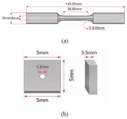
Geometry of specimens for (a) slow strain rate tensile test and (b) ONH analysis.
An oxygen-nitrogen-hydrogen (ONH) analyzer was used to quantitatively analyze the hydrogen content introduced by electrochemical hydrogen charging. Considering the specimen size limitation of the ONH analyzer, the specimens for hydrogen analysis were prepared with dimensions of , and the hydrogen content in the specimens was measured after hydrogen charging. The geometry of the specimens used for hydrogen analysis is shown in Figure 1(b).
To minimize the influence of the specimen surface condition on the hydrogen charging behavior, all specimens were ground with SiC paper up to #2000 grit under identical conditions. This minimized differences in surface-related variables, such as surface roughness, surface defects, and oxide layer, thereby enabling a comparison of the hydrogen uptake and mechanical behavior with respect to the area ratio.
2.2 Electrochemical Hydrogen Charging
Figure 2 shows the overall experimental procedure performed in this study. After specimen preparation, electrochemical hydrogen charging was performed, and the charged specimens were used for hydrogen content measurement by ONH analysis and mechanical behavior evaluation by SSRT. To analyze the influence of the area of the platinum mesh counter electrode on the hydrogen uptake and mechanical behavior of the specimen serving as the working electrode, the area ratio between the WE and CE was set as the primary experimental variable in this study.
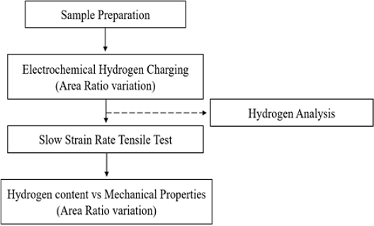
Experimental procedure for electrochemical hydrogen charging, hydrogen content measurement, and mechanical evaluation
The conditions for electrochemical hydrogen charging and mechanical property evaluation are summarized in Table 2. To avoid confusion in the notation of the area ratio, the ratio of the effective exposed area of the specimen to the effective reaction area of the platinum mesh was defined as WE:CE in this study. Accordingly, the WE:CE ratios were set to 1:1, 1:2, 1:4, 1:10, corresponding to conditions in which the effective reaction area of the platinum mesh was 1, 2, 4, and 10 times the effective exposed area of the specimen, respectively.
Test matrix for hydrogen content analysis and SSRT according to current density and WE:CE area ratio.
A platinum mesh with dimensions of 100 200 mm, composed of platinum wires with a diameter of 0.138 mm, was used as the counter electrode. The platinum mesh was cut to match the designated area ratios, and its effective reaction area was calculated by considering the porosity and geometric configuration of the mesh structure. The platinum mesh used in this study has a woven mesh structure, and Figure 3 presents a schematic diagram distinguishing the intersecting and independent (non-intersecting) segments of the mesh. The independent segments were assumed to be cylindrical, and the total surface area of the platinum mesh was calculated using Equation (1), taking into account the surface areas of the free and intersecting segments, respectively [10]. Note that the area calculated in this study is a geometric surface area intended for relative comparison among the electrode area ratio conditions, and the electrochemically active surface area (ECSA) was not separately quantified.
| (1) |
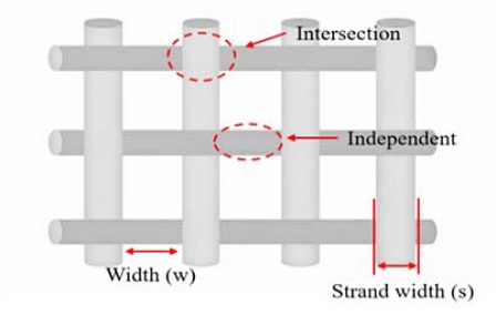
Schematic illustration of the woven platinum mesh structure showing intersection and independent strand regions
where Amesh is the surface area of the woven platinum mesh (cm2), n is the number of pores per unit length (cm-1), s is the strand width (cm), and w is the pore width (cm).
The current density was determined based on the effective exposed area of the specimen, and two conditions of 0.5 mA/cm² and 4 mA/cm² were applied. The hydrogen charging time was maintained at 72 h for all conditions. This was selected based on previous studies reporting that diffusible hydrogen in austenitic stainless steels saturates after more than 48 h of charging [12][13] and on our preliminary tests, to ensure a sufficiently saturated and comparable condition across all area ratios. ONH measurements were conducted under both current densities, whereas SSRT was performed only under 0.5 mA/cm². Since a previous study reported that hydrogen-induced degradation levels off above 1 mA/cm² with little further current-density dependence [12], the 0.5 mA/cm² condition was selected for SSRT to more clearly reveal differences associated with the area ratio.
To minimize geometric variables other than the electrode area ratio, the cell configuration was kept consistent within each test type. For the hydrogen content (ONH) tests, approximately 250 mL of electrolyte was used with an inter-electrode distance of about 5 cm between the specimen and the platinum mesh. For the SSRT tests, approximately 500 mL of electrolyte was used with an inter-electrode distance of about 4 cm. In this way, geometric factors other than the WE:CE area ratio were minimized.
2.3 Experimental Setup
Electrochemical hydrogen charging was performed using a potentiostat(WBC3000S, WonATech). Figure 4 shows the configuration of the electrochemical hydrogen charging apparatus and the electrode connections used in this study. The specimen was connected as the cathode and the platinum mesh as the anode, and hydrogen charging was conducted under galvanostatic conditions.
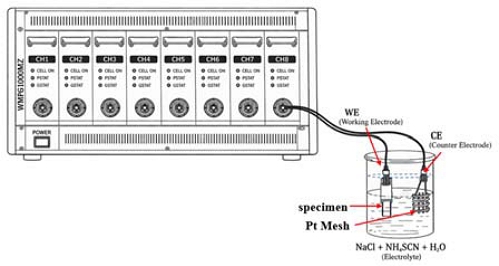
Schematic illustration of the electrochemical hydrogen charging setup using a potentiostat
Figure 5 shows the main equipment used for hydrogen content analysis and mechanical property evaluation. The hydrogen content in the specimens after hydrogen charging was measured using an ONH analyzer (ONH2000, ELTRA), as shown in Figure 5(a). A graphite crucible was used for the analysis, and the specimen was melted in a high-temperature furnace. During this process, the hydrogen present in the specimen is released in gaseous form and detected by a thermal conductivity detector. Using this equipment, the hydrogen content in the specimens after charging was quantitatively evaluated.
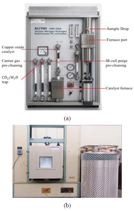
Experimental equipment used in this study: (a) ONH analyzer and (b) universal testing machine for SSRT
The mechanical behavior was evaluated using a universal testing machine (KSU-5M, Kyung Sung), as shown in Figure 5(b). The strain rate was set to 5 × 10⁻⁵ s-1. In addition, to ensure the accuracy of strain measurement, an extensometer with a gauge length of 25 mm was used to measure the deformation behavior of the specimen during the tensile tests.
3. Results and Discussion
3.1 Variation of Hydrogen Concentration with WE:CE Area Ratio
Figure 6 and Table 3 show the variation in hydrogen content of the STS 304L specimens with respect to the WE:CE area ratio. For each condition, hydrogen charging and ONH analysis were repeated three to four times, and the results are presented as the mean ± standard deviation. Under both the 0.5 and 4 mA/cm² conditions, the hydrogen content varied with the area ratio. It should be noted that the hydrogen contents under the 0.5 and 4 mA/cm² conditions were measured in different analysis batches; therefore, the results were interpreted primarily in terms of the relative trends with respect to the area ratio within each current density condition, rather than by direct comparison of the absolute hydrogen contents between the two current densities.
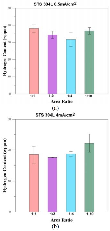
Hydrogen content of STS 304L specimens after electrochemical hydrogen charging at different electrode area ratios: (a) 0.5 mA/cm² and (b) 4 mA/cm². Error bars represent one standard deviation (n = 3-4 per condition)
Hydrogen content of STS 304L specimens according to WE:CE area ratio and current density (mean ± standard deviation)
Under the 1:1 area ratio condition, relatively high hydrogen contents were measured at both current densities. Since the effective exposed area of the specimen and the applied current density were kept constant, the total current applied to the specimen remained the same within each current density condition. However, when the CE area is relatively small, the current density on the counter electrode increases, which can alter the polarization of the CE, the cell voltage and the surface reaction state of the electrode. For Pt counter electrodes, it has been reported that Pt dissolution can occur as surface oxidation-reduction reactions intensify [14][15]. Therefore, the high hydrogen content measured under the 1:1 area ratio condition may have resulted from elevated current density on the counter electrode due to its small area and the associated changes in electrode condition, which may have indirectly influenced the hydrogen adsorption and absorption behavior on the WE surface. However, since the amount of Pt dissolution, electrode potential, and cell voltage variations were not directly quantified in this study, this interpretation should be regarded as one possible explanation rather than a definitive conclusion.
In contrast, under the 1:2, 1:4 area ratio conditions, the hydrogen content decreased compared with that under the 1:1 condition. This may be associated with to be because the current density on the counter electrode decreased with increasing CE area, thereby relatively mitigating the polarization and potential variation of the CE. In this case, the likelihood of excessive oxidation-reduction reactions and dissolution on the Pt surface is reduced, and the electrochemical hydrogen charging environment can be maintained relatively stable. Therefore, the 1:2 and 1:4 conditions may be advantageous over the 1:1 condition in terms of electrode stability and test reproducibility.
Meanwhile, under the 1:10 area ratio condition, the hydrogen content tended to increase again. This result is more reasonably interpreted as arising not from a direct effect of enhanced reaction activity on the CE itself, but from changes in the current distribution within the cell, the solution resistance, the electric field distribution between the electrodes, and the local reaction conditions on the WE surface caused by the substantially enlarged counter electrode area. In the electrochemical hydrogen charging configuration of this study, the specimen serves as the cathode; therefore, the hydrogen evolution reaction and hydrogen adsorption occur primarily on the WE surface. These observations suggest that the increase in hydrogen content under the 1:10 condition may be associated with the indirect influence of the enlarged counter electrode area on the hydrogen adsorption and absorption conditions at the WE surface, rather than from an enhancement of the HER activity of the CE itself.
Consequently, the hydrogen content varied with the WE:CE area ratio during electrochemical hydrogen charging. These variations suggest that the area ratio can act as a geometric factor influencing the charging condition - for example, when the CE area is excessively small, the electrode condition may become unstable owing to the high current density and polarization of the counter electrode, whereas when the CE area is excessively large, the current distribution within the cell and the reaction conditions on the WE surface may also be altered.
3.2 Slow Strain Rate Tensile Test Evaluation of Mechanical Behavior
Figure 7 shows the SSRT results of the STS 304L specimens hydrogen-charged under 0.5 mA/cm2 condition with area ratios of 1:1, 1:2, 1:4 and 1:10. In this section, the influence of the electrode area ratio on the mechanical behavior is examined based on the SSRT results obtained under the 0.5 mA/cm2 condition, as presented in Figure 7.
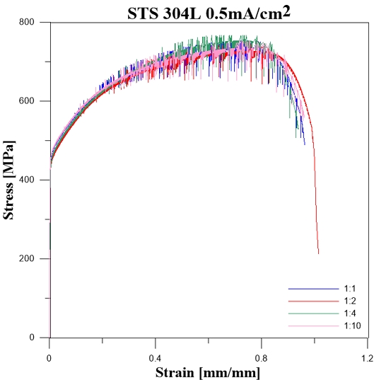
Stress-strain curves of STS 304L specimens hydrogen-charged at 0.5 mA/cm² with different area ratios
The yield strength and tensile strength were similar across all area ratio conditions, and no distinct differences were observed in the overall shape of the stress-strain curves or the work hardening behavior. The 1:1 condition exhibited a relatively larger fracture strain than the other conditions, whereas the fracture strain and the shape of the stress-strain curves were similar among the 1:2, 1:4, and 1:10 conditions. These results indicate that, although the total hydrogen content measured by ONH analysis differed with the area ratio, no distinct differences in mechanical behavior were observed under the SSRT conditions of this study.
These observations suggest that the differences in total hydrogen content measured by ONH analysis may not necessarily correspond to differences in the effective hydrogen content that directly contributes to the degradation of mechanical properties. In general, hydrogen in metals can be classified into diffusible hydrogen and non-diffusible or strongly trapped hydrogen [16]. Diffusible hydrogen can migrate relatively freely through interstitial lattice sites and can be released relatively quickly through the specimen surface at room temperature. Therefore, even if differences in the total hydrogen content exist immediately after charging, the amount of hydrogen remaining in the specimen and affecting the mechanical behavior at the time of tensile testing may be limited.
In contrast, hydrogen trapped at sites such as grain boundaries, dislocations, precipitates, or other defects can remain relatively stable and may be more directly involved in the degradation of mechanical properties and hydrogen embrittlement behavior [17][18]. The observation that the total hydrogen content varied with the area ratio while the SSRT results showed no substantial difference in yield strength and tensile strength or overall deformation behavior indicates that the amount or distribution of hydrogen substantially affecting the mechanical behavior may not have differed significantly among the area ratio conditions.
These observations suggest that the electrode area ratio acted as a influenced the total hydrogen content during electrochemical hydrogen charging, whereas its influence on the yield strength, tensile strength, and overall mechanical behavior was limited under the 0.5 mA/cm2 SSRT condition of this study. In future work, the influence of the area ratio on hydrogen embrittlement behavior should be evaluated more quantitatively by examining the elapsed time between charging and testing, separate analyses of diffusible and trapped hydrogen (e.g., thermal desorption analysis), fractographic observations, and SSRT results under higher hydrogen charging condition.
4. Conclusion
In this study, the influence of the electrode area ratio on the hydrogen uptake and mechanical behavior of STS 304L austenitic stainless steel during electrochemical hydrogen charging was experimentally investigated. The area ratios were set to 1:1, 1:2, 1:4, and 1:10, corresponding to conditions in which the effective reaction area of the platinum mesh was 1, 2, 4, and 10 times the effective exposed area of the specimen, respectively. The current densities were set 0.5 and 4 mA/cm2 based on the effective exposed area of the specimen, and the hydrogen content was quantitatively evaluated by ONH analysis. In addition, SSRT was performed on the specimens hydrogen-charged under the 0.5 mA/cm2 condition to examine the influence of the area ratio on the mechanical behavior. The main conclusions derived from this study are as follows:
- · The hydrogen content of the STS 304L specimens varied with the electrode area ratio, indicating that the area ratio between the counter and working electrodes is a key experimental variable affecting the hydrogen uptake in electrochemical hydrogen charging.
- · Under the 1:1 area ratio condition, relatively high hydrogen contents were measured at both current densities of 0.5 and 4 mA/cm2. This may be associated with the elevated current density, polarization, and surface condition changes of the counter electrode, resulting from its small area, indirectly influenced the hydrogen adsorption and absorption behavior on the WE surface.
- · Under the 1:2 and 1:4 conditions, the hydrogen content decreased compared with that under the 1:1 condition. This may be attributed to the reduced current density and mitigated polarization of the counter electrode with increasing CE area, which relatively stabilized the electrochemical charging environment.
- · Under the 1:10 condition, the hydrogen content tended to increase again. This result is attributed not to a direct enhancement of the hydrogen evolution reaction on the CE surface, but to changed in the current distribution within the cell, the solution resistance, the electric field distribution between the electrodes, and the local reaction conditions on the WE surface caused by the enlarged counter electrode area, which influenced the hydrogen adsorption and absorption behavior.
- · Although the total hydrogen content differed with the area ratio, the SSRT results under the 0.5 mA/cm2 condition showed no distinct differences in yield strength, tensile strength, or overall mechanical behavior. This suggests that the differences in total hydrogen content measured by ONH analysis may not necessarily translate directly into the degradation of mechanical properties.
The results of this study indicate that the WE:CE area ratio can influence the hydrogen uptake in electrochemical hydrogen charging tests and should therefore be explicitly controlled and reported to improve reproducibility. In future work, the influence of the area ratio on hydrogen charging and hydrogen embrittlement behavior will be investigated more quantitatively by monitoring the electrode potential and cell voltage, examining possible Pt dissolution, and separately analyzing the diffusible and trapped hydrogen through thermal desorption analysis (TDA) and hydrogen permeation testing. In addition, fractographic (SEM) observation and evaluation of the mechanical behavior under various hydrogen charging conditions will be conducted as follow-up research.
Acknowledgments
This work was supported by the Technology Innovation Program (RS-2024-00430799) funded by the Ministry of Trade, Industry & Energy(MOTIE, Korea). This work was supported by the Materials/Parts Technology Development Program (20019513, Performance verification of Mock-up considering operating environment of vessel and cargo containment system) funded By the Ministry of Trade, Industry & Energy(MOTIE, Korea).
Author Contributions
Conceptualization, S. B. Im and H. T. Kim; Methodology, J. M. Lee and H. T. Kim; Investigation, S. B. Im; Resources, J. H. Kim; Data Curation S. B. Im; Writing-Original Draft Preparation, S. B. Im; Writing-Review & Editing, J. H. Kim; Visualization, S. B. Im; Supervision, J. M. Lee; Project Administration, J. M. Lee; Funding Acquisition, J. H. Kim and J. M. Lee.
References
-
M. A. Rosen and S. Koohi-Fayegh, “The prospects for hydrogen as an energy carrier: an overview of hydrogen energy and hydrogen energy systems,” Energy, Ecology and Environment, vol. 1, no. 1, pp. 10-29, 2016.
[https://doi.org/10.1007/s40974-016-0005-z]

-
J. -S. Hwang, J. H. Kim, S. K. Kim, and J. M. Lee, “Effect of PTFE coating on enhancing hydrogen embrittlement resistance of stainless steel 304 for liquefied hydrogen storage system application,” International Journal of Hydrogen Energy, vol. 45, no. 15, pp. 9149-9161, 2020.
[https://doi.org/10.1016/j.ijhydene.2020.01.104]
-
S. -G. Kim, S. -H. Shin, and B. Hwang, “Machine learning approach for prediction of hydrogen environment embrittlement in austenitic steels,” Journal of Materials Research and Technology, vol. 19, pp. 2794-2798, 2022.
[https://doi.org/10.1016/j.jmrt.2022.06.046]
-
H. S. Yun, S. K. Jeon, Y. -K. Lee, J. S. Park, and S. H. Nahm, “Effect of precharging methods on the hydrogen embrittlement of 304 stainless steel,” International Journal of Hydrogen Energy, vol. 50, part A, pp. 175-188, 2024.
[https://doi.org/10.1016/j.ijhydene.2023.09.073]
-
S. Asante-Okyere, R. A. Mensah, J. Sandstrom, and M. Forsth, “Risk and safety assessment of hydrogen pipelines and storage tanks using preliminary hazard analysis,” Frontiers in Chemical Engineering, vol. 7, p. 1722173, 2025.
[https://doi.org/10.3389/fceng.2025.1722173]
-
Q. Li, H. Ghadiani, V. Jalilvand, T. Alam, Z. Farhat, and Md. A. Islam, “Hydrogen impact: A review on diffusibility, embrittlement mechanisms, and characterization,” Materials, vol. 17, no. 4, p. 965, 2024.
[https://doi.org/10.3390/ma17040965]
- B. Yanachkov, L. Drenchev, and L. Lyutov, “Optimizing tensile testing: the role of electrochemical in-situ charging in hydrogen-metal interaction research,” Machines. Technologies. Materials., vol. 18, no. 5, pp. 160-162, 2024.
-
R. N. Iyer, H.W. Pickering, and M. Zamanzadeh, “A mechanistic analysis of hydrogen entry into metals during cathodic hydrogen charging,” 1988.
[https://doi.org/10.1016/S0036-9748(88)80074-7]
-
L. Cupertino-Malheiros, M. Duportal, T. Hageman, A. Zafra, and E. Martínez-Pañeda, “Hydrogen uptake kinetics of cathodic polarized metals in aqueous electrolytes,” Corrosion Science, vol. 231, p. 111959, 2024.
[https://doi.org/10.1016/j.corsci.2024.111959]
-
H. I. Lee, et al., “The structural effect of electrode mesh on hydrogen evolution reaction performance for alkaline water electrolysis,” Frontiers in Chemistry, vol. 9, p. 787787, 2021.
[https://doi.org/10.3389/fchem.2021.787787]
-
T.-W. Kim, et al., “A study on the effect of hydrogen embrittlement and temperature of welds in steel applied to liquid hydrogen storage systems,” Journal of Welding and Joining, vol. 43, no. 3, pp. 260-266, 2025.
[https://doi.org/10.5781/JWJ.2025.43.3.4]
-
B. -K. Hwang, et al., “Comparative study of hydrogen embrittlement in 310S, 304L, and 316L stainless steels under in situ electrochemical hydrogen charging. Part 1: Experimental study,” Engineering Failure Analysis, vol. 176, pp. 109641, 2025.
[https://doi.org/10.1016/j.engfailanal.2025.109641]
-
D. Pałgan, M. Uhlirsch, N. Fuertes, and B. Sefer, “Comparative study of hydrogen uptake in low alloyed carbon and austenitic stainless steels under cathodic hydrogen charging in aqueous electrolyte and gaseous hydrogen charging,” Procedia Structural Integrity, vol. 54, pp. 322-331, 2024.
[https://doi.org/10.1016/j.prostr.2024.01.090]
-
Y. Zhang, M. D. Merrill, and B. E. Logan, “The use and optimization of stainless steel mesh cathodes in microbial electrolysis cells,” International Journal of Hydrogen Energy, vol. 35, no. 21, pp. 12020-12028, 2010.
[https://doi.org/10.1016/j.ijhydene.2010.08.064]
-
M. Tian, et al., “Influence of the working and counter electrode surface area ratios on the dissolution of platinum under electrochemical conditions,” ACS Catalysis, vol. 6, no. 8, pp. 5108-5116, 2016.
[https://doi.org/10.1021/acscatal.6b00200]
-
O. Barrera, et al., “Understanding and mitigating hydrogen embrittlement of steels: a review of experimental, modelling and design progress from atomistic to continuum,” Journal of Materials Science, vol. 53, no. 9, pp. 6251-6290, 2018.
[https://doi.org/10.1007/s10853-017-1978-5]
-
A. Islam, et al., “Effect of microstructure on hydrogen permeation and trapping in natural gas pipeline steels,” npj Materials Degradation, vol. 9, no. 1, Art. 70, 2025.
[https://doi.org/10.1038/s41529-025-00615-5]
-
T. Boot, et al., “Effect of plastic deformation on the hydrogen embrittlement of ferritic high strength steel,” npj Materials Degradation, vol. 9, no. 1, Art. 39, 2025.
[https://doi.org/10.1038/s41529-025-00592-9]