
Flow characteristics and predictive correlations within adiabatic capillaries for R290 refrigeration systems

Copyright © The Korean Society of Marine Engineering
This is an Open Access article distributed under the terms of the Creative Commons Attribution Non-Commercial License (http://creativecommons.org/licenses/by-nc/3.0), which permits unrestricted non-commercial use, distribution, and reproduction in any medium, provided the original work is properly cited.
Abstract
This study aimed to theoretically identify and analyze the factors influencing the flow characteristics within adiabatic capillaries using R290 refrigerant in a refrigeration system, and based on this, propose a correlation equation for predicting capillary length. The main results can be summarized as follows. At the same refrigerant flow rate, the required capillary length tended to increase as the condensation temperature increased. On the other hand, under conditions where the condensation temperature was maintained constant, the required capillary length gradually increased as the refrigerant flow rate decreased. Furthermore, under the same refrigerant flow rate conditions, the total required capillary length tended to increase as the degree of subcooling increased. Under conditions where the degree of subcooling was maintained constant, it was confirmed that the required capillary length increased as the refrigerant mass flow rate decreased. When the refrigerant mass flow rate was constant, the required capillary length increased as the inner diameter of the capillary increased. Additionally, under the same pipe diameter conditions, the capillary length tended to increase as the refrigerant mass flow rate decreased. In this study, a predictive correlation equation capable of calculating the total length of the capillary tube from conditions such as refrigerant flow rate, condensation temperature, evaporation temperature, inlet subcooling, and capillary tube diameter was proposed as basic design data for an adiabatic capillary tube in a refrigeration system for R290.
Keywords:
Adiabatic capillary tube, Flow characteristics, Predictive correlation, R290, Vapor compression system1. Introduction
The adiabatic capillary tube is one of the most widely used expansion devices in refrigeration systems because it regulates the refrigerant mass flow rate by utilizing the pressure difference between the condenser and the evaporator. The geometric dimensions of the capillary tube directly affect the refrigerant flow characteristics and consequently influence the cooling capacity, energy efficiency, and overall performance of the refrigeration system. In particular, because the natural refrigerant R290 possesses thermophysical properties that differ significantly from those of conventional hydrofluorocarbon (HFC) refrigerants, the capillary tube length and inner diameter must be properly designed to achieve the desired refrigeration capacity. Accordingly, considerable research has been conducted to investigate the flow characteristics inside adiabatic capillary tubes and to develop reliable methods for predicting the optimum capillary tube length.
Early studies primarily focused on developing analytical models for predicting the pressure drop and refrigerant mass flow rate in adiabatic capillary tubes. Pate and Rupasinghe [1] proposed a one-dimensional steady-state analytical model for alternative refrigerants based on the Homogeneous Flow Model (HFM), in which the refrigerant flow was analyzed using the conservation equations of mass, momentum, and energy. Subsequently, Rupasinghe [2] developed an analytical model that simultaneously considered frictional pressure loss and acceleration pressure loss by treating the two-phase refrigerant flow as a homogeneous mixture. Melo et al. [3] experimentally measured the pressure distribution and refrigerant mass flow rate inside capillary tubes for various refrigerants and validated the predictive capability of the HFM-based analytical model. These studies established the theoretical foundation for analyzing refrigerant flow in adiabatic capillary tubes and continue to serve as the basis for capillary tube design and performance analysis.
Since the early 2000s, increasing environmental regulations have accelerated the application of natural refrigerants, leading to extensive investigations of R290 refrigeration systems. Compared with conventional R134a, R290 has lower viscosity, higher latent heat of vaporization, and lower density. Consequently, different capillary tube dimensions are required to achieve the same refrigeration capacity. Previous studies have reported that R290 generally requires a shorter capillary tube than R134a under identical operating conditions. Furthermore, the refrigerant undergoes subcooled liquid flow followed by flashing inside the capillary tube, eventually developing into a two-phase flow. Most of the total pressure drop occurs in the two-phase flow region, making its flow characteristics one of the most important factors governing the refrigerant mass flow rate and refrigeration system performance.
Numerous investigations have also examined the effects of operating parameters on the flow characteristics of adiabatic capillary tubes. It has generally been reported that increasing the condensation temperature increases the refrigerant mass flow rate, whereas decreasing the evaporation temperature increases the pressure difference across the capillary tube, thereby altering the flow behavior. An increase in inlet subcooling delays the onset of flashing, moving the flashing point toward the downstream end of the capillary tube. In addition, increasing the tube diameter decreases the pressure drop while increasing the refrigerant mass flow rate. Conversely, increasing the capillary tube length increases the frictional pressure loss, thereby reducing the refrigerant mass flow rate. These findings indicate that condensation temperature, evaporation temperature, inlet subcooling, tube diameter, and capillary tube length are the primary design parameters governing the performance of adiabatic capillary tubes, with tube diameter and tube length being particularly important.
To improve capillary tube design accuracy, several empirical and semi-empirical correlations have been proposed to predict the required capillary tube length. Choi et al. [4] developed a dimensionless correlation based on the Buckingham π theorem using experimental data for several refrigerants, including R22, R290, and R407C. Their correlation achieved an average prediction error of approximately 1% and has been widely adopted for practical capillary tube design. Trisaksri and Wongwises [5] also proposed a prediction correlation incorporating condensation temperature, evaporation temperature, inlet subcooling, capillary tube diameter, and refrigerant mass flow rate, thereby providing a practical design tool for refrigeration systems.
Yang and Wang [6] subsequently developed a generalized correlation based on the Homogeneous Flow Model that is applicable to various refrigerants, including R12, R22, R134a, R290, R600a, R404A, R407C, and R410A. Their correlation exhibited an average deviation of approximately –0.8% and a standard deviation of about 9%, and it remains one of the representative predictive models for refrigerant mass flow rate. In Korea, Lim [7] employed the Engineering Equation Solver (EES) [8] to predict capillary tube lengths by iteratively solving the governing equations of mass, momentum, and energy conservation. The results indicated that R290 requires a capillary tube approximately 20–22% shorter than that required for R134a under the same refrigeration capacity because of its superior thermophysical properties.
Bose et al. [9] numerically simulated the expansion of R-290 through a 1.2 mm diameter spiral capillary tube using a finite volume-based mixing model. ANSYS Fluent software was used for the numerical simulation. The effects of tube length, condenser and evaporator pressures on mass transfer rate, evaporator inlet temperature, mixture dryness at the evaporator inlet, and effective cooling effect were analyzed.
These previous studies have significantly contributed to the understanding of refrigerant flow behavior in adiabatic capillary tubes and have provided useful analytical models and design correlations based on the Homogeneous Flow Model. They also demonstrated that the capillary tube design for natural refrigerants such as R290 differs considerably from that for conventional HFC refrigerants because of the differences in thermophysical properties and flow characteristics.
Previous studies have already established the homogeneous flow model as an effective engineering approach for capillary-tube analysis. Although the HFM neglects slip and thermal non-equilibrium effects, it remains one of the most widely adopted design methods because of its simplicity and computational efficiency. Accordingly, the present study focuses on developing a practical prediction correlation based on the conventional HFM framework.
Although the HFM adopted in this study follows the conventional analytical framework proposed in previous investigations, the objective of the present study is different. Rather than developing a new two-phase flow model, this study establishes a practical regression correlation for predicting the required capillary tube length of R290 over a wide operating range. The proposed correlation is intended to provide engineering design data for practical refrigeration applications.
2. Mathematical Model
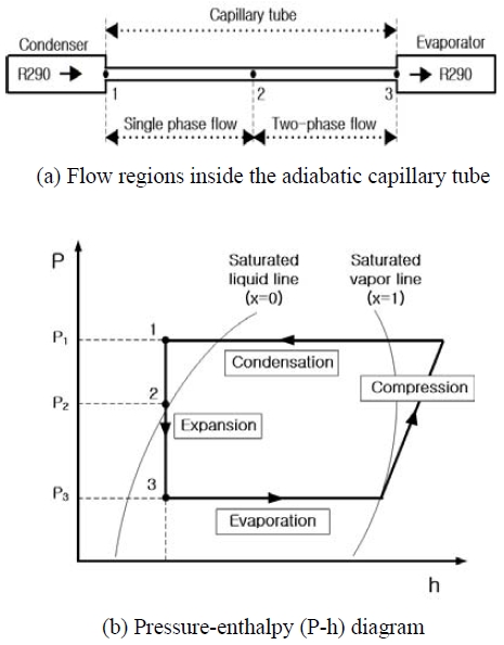
The governing equations and numerical solution procedure adopted in the present study are based on the homogeneous flow model proposed by Lim [7], with modifications for the operating conditions considered in the present investigation. The refrigerant flow through an adiabatic capillary tube can generally be divided into two distinct regions: a single-phase flow region and a two-phase flow region. As illustrated in Figure 1 (a), the refrigerant enters the capillary tube as a subcooled liquid and first passes through the single-phase flow region (State 1 → State 2). As the refrigerant pressure continuously decreases along the tube, flashing occurs at the saturation point, and the flow subsequently changes into a two-phase mixture (State 2 → State 3). Therefore, the total length of the capillary tube,Lcap, can be expressed as the sum of the lengths of the single-phase flow region, Lsp, and the two-phase flow region, Ltp.
Flow regions inside the adiabatic capillary tube and the corresponding pressure-enthalpy (P-h) diagram
Figure 1 (b) presents the pressure-enthalpy (P-h) diagram corresponding to the expansion process inside the adiabatic capillary tube. The thermodynamic state of the refrigerant during the throttling process can be clearly identified from the P–h diagram.
- ● In the present study, the Engineering Equation Solver was employed to calculate the thermophysical properties of R290 and to perform the numerical analysis of refrigerant flow through the adiabatic capillary tube. To simplify the mathematical formulation, the following assumptions were adopted.
- ● The capillary tube is assumed to be a straight horizontal tube with a constant inner diameter and uniform surface roughness.
- ● The refrigerant flow is assumed to be one-dimensional, steady-state, and homogeneous throughout the capillary tube.
- ● The expansion process inside the capillary tube is assumed to be an adiabatic throttling process with constant total enthalpy, neglecting both heat transfer to the surroundings and shaft work.
- ● The working fluid is assumed to be pure R290 without any dissolved lubricating oil.
- ● The refrigerant flow inside the capillary tube is assumed to remain fully developed and turbulent over the entire flow path.
- ● Minor pressure losses at the capillary tube inlet are neglected.
Based on the above assumptions, the flow characteristics of R290 inside the adiabatic capillary tube were analyzed using the conservation equations of mass, momentum, and energy. The refrigerant flow was modeled using the Homogeneous Flow Model (HFM), in which the liquid and vapor phases are assumed to be in thermodynamic equilibrium and to travel at the same velocity. This assumption is considered appropriate for R290 because its relatively high latent heat of vaporization results in a smaller refrigerant charge than that required for conventional HFC refrigerants under the same refrigeration capacity. Consequently, the velocity difference between the liquid and vapor phases is relatively small, allowing the homogeneous flow model to reasonably represent the actual two-phase flow behavior under the operating conditions considered in this study [4][5][10][11][12][13].
2.1 Single Phase Flow Region
Assuming steady-state flow through an infinitesimal control volume inside the capillary tube, the conservation of mass yields the following relationship:
| (1) |
Using Equation (1), the refrigerant velocity can be expressed as
| (2) |
Since the capillary tube is installed horizontally, the change in potential energy can be neglected (dz=0). Furthermore, assuming an adiabatic steady-flow process with no heat transfer to the surroundings and no shaft work, the energy conservation equation can be combined with Equation (2) to give
| (3) |
The momentum change of the refrigerant flowing through the capillary tube is analyzed using the momentum conservation equation. Because the capillary tube is horizontal, the body force associated with elevation changes is negligible (sin Θ). Consequently, only the pressure gradient and the wall friction force are considered, and the momentum equation can be written as
| (4) |
Rearranging Equation (4) with respect to the capillary tube length yields
| (5) |
For the single-phase flow region, the friction factor was calculated using the Churchill [10] correlation recommended by W. T. Lim [7], which is applicable over a wide range of Reynolds numbers and relative roughness. The friction factor is given by
| (6) |
where
| (7) |
2.2 Two-Phase Flow Region
For the two-phase flow region, the same assumptions adopted for the single-phase flow region were applied. Since the capillary tube is installed horizontally, the change in potential energy was neglected, and the refrigerant expansion process was assumed to be a steady-state adiabatic flow without external work. Under these assumptions, the energy conservation equation for the two-phase flow region can be expressed as
| (8) |
The specific enthalpy and specific volume of the two-phase refrigerant mixture are defined as
| (9) |
By combining Equations (8) and (9), the length of the capillary tube in the two-phase flow region can be expressed as
| (10) |
The friction factor for the two-phase flow region was evaluated using the Churchill correlation, which was also employed for the single-phase flow analysis. Accordingly, the friction factor is given by
| (11) |
where the dimensionless parameters used in the Churchill correlation are defined as
| (12) |
The viscosity of the two-phase refrigerant under homogeneous flow conditions was evaluated using the McAdams viscosity model, which has been recommended by Bittle and Pate [1] because of its computational efficiency and satisfactory prediction accuracy. The corresponding relationship is expressed as
| (13) |
2.3 Numerical Procedure
The numerical procedure follows the solution method proposed by Lim [7]. The present study employs the same solution framework while generating a new numerical database covering wider operating conditions for regression analysis. The calculation started from the condenser pressure at the capillary tube inlet (P1) and proceeded iteratively until the evaporator pressure at the tube outlet (P3) was reached.
For the numerical calculation, the capillary tube was discretized into a series of control volumes with an axial length of 1 mm. The pressure and temperature at the outlet of each control volume were successively calculated from those at the inlet. The thermophysical properties of R290, including density, specific volume, and dynamic viscosity, were evaluated using the average pressure and temperature of each control volume. These properties were subsequently employed as the input conditions for the following computational step. This numerical procedure was repeated along the entire capillary tube until the prescribed outlet pressure was satisfied.
2.4 Operating Conditions
The operating conditions adopted in the present numerical analysis are summarized in Table 1. The calculation conditions were selected based on the typical operating range of an R290 refrigeration system.

Range of operating conditions used for the performance analysis of the R290 adiabatic capillary tube
Using the operating conditions listed in Table 1, the governing equations together with the thermophysical properties of R290 were solved numerically to investigate the flow behavior and performance characteristics of the adiabatic capillary tube. The effects of condensation temperature, evaporation temperature, inlet subcooling, and capillary tube diameter on the internal flow characteristics were systematically analyzed. Furthermore, the influences of these parameters on the pressure drop, refrigerant mass flow rate, and optimum capillary tube length were quantitatively evaluated and discussed.
3. Results and Discussion
3.1 Effect of Evaporation Temperature
The influence of evaporation temperature on the required length of the R290 adiabatic capillary tube was investigated under various operating conditions. During the analysis, the capillary tube diameter, condensation temperature, inlet subcooling, and tube roughness were maintained constant, while the evaporation temperature was varied within the prescribed operating range.
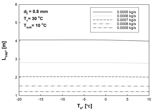
Figure 2 illustrates the variation in capillary tube length with evaporation temperature. For a constant refrigerant mass flow rate, the required capillary tube length remained almost unchanged as the evaporation temperature increased. This indicates that the evaporation temperature has a relatively small influence on the overall capillary tube length under the investigated operating conditions.
Effect of evaporation temperature on the length of the R290 adiabatic capillary tube
The reason for this behavior is that the pressure difference between the condenser and evaporator decreases with increasing evaporation temperature, whereas the density difference between the liquid and vapor phases simultaneously increases because of the reduction in vapor quality at the capillary tube outlet. These two opposing effects compensate each other, resulting in only a minor variation in the total capillary tube length.
On the other hand, when the evaporation temperature was fixed, the required capillary tube length increased as the refrigerant mass flow rate decreased. This tendency is attributed to the reduced pressure loss associated with lower refrigerant velocity, requiring a longer capillary tube to achieve the desired pressure drop.
3.2 Effect of Condensation Temperature
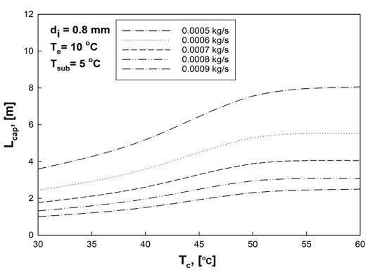
The effect of condensation temperature on the required capillary tube length is presented in Figure 3. The tube diameter, evaporation temperature, inlet subcooling, and tube roughness were maintained constant during the analysis.
Effect of condensation temperature on the length of the R290 adiabatic capillary tube
For a constant refrigerant mass flow rate, the capillary tube length increased continuously as the condensation temperature increased. Since a higher condensation temperature produces a higher condensation pressure, the pressure difference across the capillary tube becomes larger. Consequently, a longer capillary tube is required to generate the increased pressure drop under identical operating conditions.
In contrast, when the condensation temperature remained constant, the capillary tube length increased as the refrigerant mass flow rate decreased. This phenomenon is consistent with the pressure drop characteristics of capillary tubes and has also been reported by Bansal and Rupasinghe [2]. Overall, condensation temperature was found to be one of the most influential parameters affecting the required capillary tube length.
3.3 Effect of Inlet Subcooling
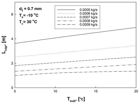
Figure 4 presents the influence of inlet subcooling on the capillary tube length.
Effect of inlet subcooling on the length of the R290 adiabatic capillary tube
For a fixed refrigerant mass flow rate, the capillary tube length increased with increasing inlet subcooling. Increasing the inlet subcooling decreases the refrigerant temperature at the capillary tube entrance and delays the onset of flashing inside the tube. As a result, the single-phase liquid flow region becomes longer, whereas the two-phase flow region becomes shorter. Since the increase in the single-phase region is larger than the decrease in the two-phase region, the overall capillary tube length increases.
When the inlet subcooling remained constant, decreasing the refrigerant mass flow rate again resulted in a longer capillary tube because a larger tube length was required to obtain the prescribed pressure reduction.
3.4 Effect of Capillary Tube Diameter
Figure 5 shows the effect of capillary tube diameter on the required capillary tube length.
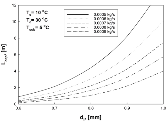
Effect of tube diameter on the length of the R290 adiabatic capillary tube
As expected, increasing the tube diameter resulted in a significant increase in the required tube length. A larger tube diameter reduces the refrigerant velocity and decreases the frictional pressure drop per unit length. Consequently, a longer capillary tube is necessary to obtain the required pressure reduction.
For each tube diameter, decreasing the refrigerant mass flow rate also increased the required capillary tube length because of the corresponding reduction in flow resistance.
Among all investigated parameters, tube diameter exhibited the greatest influence on the capillary tube length, indicating that accurate selection of the tube diameter is essential during refrigeration system design.
3.5 Development of the Regression Correlation
Although numerical analysis based on the homogeneous flow model provides accurate predictions of capillary tube performance, it requires repeated iterative calculations. Therefore, a simple regression equation was developed to facilitate rapid estimation of the required capillary tube length.
A total of 85 numerical were used for the regression analysis. These cases were obtained by combining the four single-variable parametric sweeps used in the sensitivity analyses of Section 3.1-3.4 (Figures 2-5), in which the capillary tube diameter, evaporation temperature, inlet subcooling, and condensation temperature were each varied over several discrete levels while the remaining variables were held constant, combined with five levels of refrigerant mass flow rate (0.0005–0.0009 kg/s) applied as parametric curves in each sweep. Because this procedure does not constitute a full factorial design over all five variables, it does not provide balanced coverage of all interaction effects; this is discussed further as a limitation of the regression model.
The dependent variable was the required capillary tube length. The regression equation can be expressed as a mean-centered log-quadratic regression model that exhibits superior predictive performance.
| (14) |
- where
- Lcap : capillary tube length [m]
- M : refrigerant mass flow rate [kg/s]
- Te : evaporation temperature [℃]
- Tc : condensation temperature [℃]
- Tsub : inlet subcooling [℃]
- di : capillary tube diameter [mm]
3.6 Validation of the Regression Equation
The predictive capability of the proposed correlation was evaluated using several statistical performance indices, as summarized in Table 2. The training dataset yielded a MAPE of 17.48%, while the leave-one-out cross-validation (LOOCV) produced a slightly higher MAPE of 19.24%, indicating a modest, expected increase in prediction error when each data point is excluded from training. It should be noted that this validation was conducted solely on the numerical dataset generated from the homogeneous flow model, without independent experimental data; therefore, the predictive accuracy reported here should be interpreted as an internal consistency check rather than a fully validated result against physical measurements. Within this scope, the proposed regression equation provides a reasonably consistent prediction over the investigated operating range.
Statistical performance metrics of the proposed regression model for Equation (14)
4. Conclusion
The flow characteristics of an adiabatic capillary tube for an R290 refrigeration system were numerically investigated using the homogeneous flow model (HFM). Furthermore, a multiple regression analysis was performed to develop a practical prediction equation for estimating the required capillary tube length. The major conclusions obtained from this study are summarized as follows.
The required capillary tube length was only slightly influenced by the evaporation temperature within the investigated operating range because the reduction in pressure difference was compensated by the increase in the liquid-vapor density difference.
The capillary tube length increased with increasing condensation temperature. A higher condensation temperature increased the pressure difference between the condenser and evaporator, thereby requiring a longer capillary tube to achieve the desired pressure reduction.
Increasing the inlet subcooling resulted in a longer capillary tube because the single-phase liquid flow region became longer before the onset of flashing. Conversely, the capillary tube length increased as the refrigerant mass flow rate decreased under all investigated operating conditions.
The tube diameter was found to be the most influential design parameter affecting the required capillary tube length. Larger tube diameters produced lower frictional pressure losses per unit length and therefore required significantly longer capillary tubes.
A multiple regression equation was successfully developed using the numerical database generated by the homogeneous flow model. The proposed correlation showed a log-scale coefficient of determination (R²) of 0.926 and an original-scale coefficient of determination of 0.898, with a training MAPE of 17.48% and a LOOCV MAPE of 19.24%. These results indicate a reasonably consistent internal predictive performance; however, as the validation was based only on the numerical dataset and LOOCV, without independent experimental data, further experimental verification is required before the correlation can be considered fully validated for general application.
The proposed regression equation enables rapid estimation of the required capillary tube length without repeated iterative numerical calculations. Therefore, it can serve as a practical design tool for refrigeration systems employing R290 and may contribute to improving the design efficiency of environmentally friendly refrigeration equipment.
Nomenclature
| A : | Area, [m2] |
| di : | Inner diameter, [m] |
| dP : | Pressure drop, [kPa] |
| f : | Friction factor |
| G : | Mass flux, [kg/(m2s)] |
| h : | Enthalpy, [kJ/kg] |
| L : | Length of capillary tube, [m] |
| M : | Mass flowrate, [kg/s] |
| P : | Pressure, [kPa] |
| Re : | Reynolds Number, [Gd/μ] |
| Te : | Evaporation temperature, [℃] |
| V : | Velocity, [m/s] |
| v : | Specific volume, [m3/kg] |
| x : | Quality |
| dz : | Length of subsection, [m] |
Greek Symbols
| μ : | Viscosity, [kg/(ms)] |
| ρ : | Density, [kg/m3] |
| ε : | Roughness, [m] |
| θ : | Angle, [°] |
Subscripts
| cap : | capillary tube |
| cr : | critical point |
| f : | friction |
| g : | vapor |
| in : | inlet |
| l : | liquid |
| lo : | liquid only |
| re : | refrigerant |
| sp : | single phase |
| tp : | two-phase |
Acknowledgments
The author solely conceived the study, developed the mathematical model, performed the numerical simulations and regression analysis, interpreted the results, prepared the original manuscript, revised the manuscript, and approved the final version for publication.
Author Contributions
Conceptualization, S. J. Ha; Supervision, S. J. Ha.
References
- R. R. Bittle and M. B. Pate, “Theoretical model for predicting adiabatic capillary tube performance with alternative refrigerants”, ASHRAE Transactions, vol. 102, no. 2, pp. 52-61, 1996.
-
P. K. Bansal and A. S. Rupasinghe, “An homogeneous model for adiabatic capillary tubes”, Applied Thermal Engineering, vol. 18, no. 3-4, pp. 207-219, 1998.
[https://doi.org/10.1016/S1359-4311(97)00016-1]

-
C. Melo, R. T. S. Ferreira, C. Boabaid Neto, J. M. Gonçalves, and M. M. Mezavila, “An experimental analysis of adiabatic capillary tubes”, Applied Thermal Engineering, vol. 19, no. 6, pp. 669–684, 1999.
[https://doi.org/10.1016/S1359-4311(98)00062-3]
-
J. M. Choi, Y. C. Kim, and H. Y. Kim, “A generalized correlation for refrigerant mass flow rate through adiabatic capillary tubes”, International Journal of Refrigeration, vol. 26, no. 8, pp. 881-888, 2003.
[https://doi.org/10.1016/S0140-7007(03)00079-3]
-
V. Trisaksri and S. Wongwises, “Correlations for sizing adiabatic capillary tubes”, International Journal of Energy Research, vol. 27, no. 13, pp. 1145-1164, 2003.
[https://doi.org/10.1002/er.937]
-
L. Yang and W. Wang, “A generalized correlation for the characteristics of adiabatic capillary tubes”, International Journal of Refrigeration, vol. 31, no. 2, pp. 197-203, 2008.
[https://doi.org/10.1016/j.ijrefrig.2007.06.012]
- W. T. Lim, “Prediction of adiabatic capillary tube length of small refrigeration system using natural refrigerants”, KSMAT, vol. 21, no. 3, pp. 510–516, 2019.
-
S. M. Bose, S. K. Jena, and S. D. Patle, “Numerical investigation of flashing of propane (R-290) in a helical capillary tube”, Numerical Heat Transfer, Part A: Applications, vol. 84, no. 3, pp. 219-237, 2022.
[https://doi.org/10.1080/10407782.2022.2105116]
-
S. K. Jena, S. Bose, and S. D. Patle, “Comparison of the performance of propane (R290) and propene (R1270) as alternative refrigerants for cooling during expansion in a helical capillary tube: A CFD-based insight investigation”, International Journal of Refrigeration, vol. 146, pp. 300-313, 2023.
[https://doi.org/10.1016/j.ijrefrig.2022.11.009]
-
S. Novianto, A. S. Pamitran, R. Koestoer, E. A. Kosasih, and M. I. Alhamid, “Void fraction of flow boiling with propane in circular horizontal tube”, International Journal of Technology, vol. 7, no. 2, pp. 235-243, 2016.
[https://doi.org/10.14716/ijtech.v7i2.2980]
-
C. Liu, F. Wang, Y. Gao, Y. Zheng, and R. Li, “Numerical analysis and correlation comparison of void fraction in refrigerant two-phase flow in horizontal tubes”, Applied Thermal Engineering, vol. 270, Art. 126276, 2025.
[https://doi.org/10.1016/j.applthermaleng.2025.126276]
-
K. Li, L. Peng, S. Mohtaram, X. Chen, H. Zhang, Q. Min, C. Li, L. Song, and Q. He, “Refrigerant charge optimization and thermal performance evaluation of an R290-based secondary loop system for electric vehicles”, Energy, vol. 336, Art. 138570, 2025.
[https://doi.org/10.1016/j.energy.2025.138570]
- S. W. Churchill, “Friction factor equations spans all fluid-flow regimes”, Chemical Engineering Journal, vol. 84, pp. 91-92, 1977.