
Design, optimization and structural analysis of a marine propeller for a solar-powered boat

Copyright © The Korean Society of Marine Engineering
This is an Open Access article distributed under the terms of the Creative Commons Attribution Non-Commercial License (http://creativecommons.org/licenses/by-nc/3.0), which permits unrestricted non-commercial use, distribution, and reproduction in any medium, provided the original work is properly cited.
Abstract
This study reports the design, hydrodynamic optimization, and structural assessment of a marine propeller for a solar-powered vessel. Using lifting-line model theory, the operating point was defined from the hull drag characteristics and used to develop a two-blade, 220mm diameter propeller tailored to the thrust and power constraints of the solar powered-boat. Parametric optimization and cavitation analysis were employed to identify a geometry that combines high open-water efficiency (≈ 0.80) with acceptable cavitation margins. A finite element model, with aluminium alloy 5083 as blade material, was used to verify static strength and fatigue safety, including a fillet-radius sensitivity study at the blade–hub junction. The final propeller design satisfies the thrust requirements while keeping von Mises stresses below conservative fatigue limits, and its performance curves provide guidance for propulsion system integration.
Keywords:
Solar-powered boat, Marine propeller, Hydrodynamic optimization; Cavitation; Structural analysis1. Introduction
Propellers, as the primary mechanism for converting rotational energy into thrust, operate on principles of fluid dynamics to generate pressure differences across blade surfaces [1]. The global shift toward renewable energy has spurred the development of solar-powered vessels, which impose stringent requirements on propulsion systems due to limited power availability. These vessels demand lightweight, high-efficiency propellers that optimize thrust while minimizing energy losses and structural vulnerabilities, particularly in low-speed, high-torque regimes typical of solar-powered applications.
Several works address the propeller design within the continuum of marine propulsion methodologies, emphasizing the lifting-line approach efficacy over empirical chart-based methods or Computational Fluid Dynamics (CFD) approaches. OpenProp [2] stands out as an open-source lifting-line code with vortex lattice coupling, offering modular optimization capabilities. Codes like PROCAL [3] (developed by the Cooperative Research Ships organization [4]) and MPUF-3A [5], the most recent version of PUF-3A [6] vortex/source-lattice (placed on mean camber surface) method, implement advanced vortex-lattice methods for contra-rotating and unsteady flow analysis, respectively, with rigorous validation in peer-reviewed benchmark studies [7]. Comparative studies suggest OpenProp and PROCAL offer the most transparent vortex-line implementations for research, whereas MPUF-3A remains the gold standard for unsteady hydrodynamic prediction. Epps et al. [8, 9, 2] and Bellingham et al. [10] used OpenProp for Autonomous Underwater Vehicle (AUV) propeller design, leveraging lifting-line theory to model complex inflow dynamics and enhance efficiency. Li et al. [11] applied OpenProp to optimize AUV propulsion systems, focusing on geometric parameter adjustments for improved thrust. Zhang et al. [12] designed an high-efficiency propeller for the an AUV, leveraging the lifting-line theory within the OpenProp framework, integrated with computational fluid dynamics. Recent advancements integrate machine learning (ML) to address high-dimensional design spaces. Kyung et al. [13] and Stefano et al. [14] coupled lifting-line methods with optimization algorithms, such as genetic algorithms, to refine blade geometry in non-uniform flow fields. Wang et al. [15] proposed an optimization framework combining experimental design and neural network approximations to maximize propeller efficiency. Vardhan et al. [16] introduced Surrogate-Assisted Optimization, using ML models like random forests and decision trees to model inverse problems, providing high-quality initial designs for propeller optimization, significantly reducing design time in high-dimensional spaces.
Recent studies have focused on propellers for low-power applications, such as solar-powered vessels. Jadmiko et al. [17] analyzed symmetrical blade propellers using CFD, achieving efficiencies comparable to conventional designs. Alegre [18] optimized propellers for the SR03 vessel, emphasizing cavitation reduction through chord adjustments. Materials like Aluminium 5083, with high corrosion resistance and moderate fatigue strength (125135 MPa for H111 temper), are increasingly used for lightweight marine applications [19, 20]. Structural analysis, guided by standards defined by Shigley [21], emphasized the stress concentration mitigation at blade-hub junctions via fillet reinforcement optimization.
In this work we will focus on a solar-powered boat designed for competitive and sustainable maritime applications, requires a propeller capable of delivering 260 N of thrust at a vessel speed of 7.2 m/s, operating within the constraints of a 12 kW Waterproof Brushless Motor. The main objective of this project is to design, optimize, and structurally validate a propeller for the first solar-powered competition vessel of FEUP Academic Solar Team (FAST). The goal is to develop a high-efficiency, lightweight, and structurally robust propeller capable of delivering the required thrust under defined operational conditions, while maximizing hydrodynamic performance and ensuring long term durability under load scenarios.
2. Methodology
Marine propeller design has evolved significantly, driven by advances in computational tools, materials, and the demand for energy-efficient propulsion. Propellers operate by generating thrust through the interaction of rotating blades with water, governed by hydrodynamic principles [22]. Key performance metrics include thrust coefficient (KT), torque coefficient (KQ), advance ratio (J), and open-water efficiency (η0), as defined by Carlton [1]. The Thrust Coefficient (KT) quantifies the thrust produced by the propeller in relation to its rotational speed and diameter:
| (1) |
where T is the thrust force, ρ is the fluid density, n is the rotational speed, and D is the propeller diameter. The Torque Coefficient (KQ), describes the rotational resistance experienced by the propeller:
| (2) |
where Q is the torque. The Advance Ratio (J) relates the forward velocity of the vessel to the rotational speed of the propeller:
| (3) |
where VS is the ship speed. This parameter helps determine the operating conditions of the propeller. Finally, the Open Water Efficiency (η0) expresses how effectively the propeller converts input power into useful thrust:
| (4) |
A high η0 value indicates that the propeller is efficiently generating thrust with minimal energy loss. These metrics guide design optimization to maximize efficiency while mitigating cavitation, a phenomenon where vapor bubbles form and collapse, causing erosion, noise, and efficiency losses [1].
Cavitation is a phenomenon in fluid dynamics where vapour bubbles form in a liquid due to local pressure dropping below the vapour pressure of the fluid. When these bubbles collapse, they generate high-pressure shock waves, which can cause erosion, noise, and vibration in marine propellers, impacting efficiency [2]. Phase transition is a critical factor in cavitation dynamics, with Preso et al. [23] demonstrating that higher vapor pressure in laser-induced bubbles in aqueous ammonia reduces collapse intensity and promotes spherical collapse through vapor compression, while Zhang et al. [24] highlight a comprehensive model accounting for liquid compressibility, phase transition, and migration, showing increased vapor proportion enhances energy loss and radiated pressure peaks. Cavitation types—sheet, bubble, cloud, tip vortex, and hub vortex—impact propeller performance differently [1]. Design strategies to mitigate cavitation include optimizing blade geometry (e.g., skew, rake, chord distribution), selecting appropriate pitch ratios, and using cavitation-resistant materials like Nickel-Aluminium Bronze [18]. Computational tools such as OpenProp [2], which employs lifting line theory, and computational fluid dynamics enable precise prediction of cavitation zones and performance.
2.1 Lifting Line Theory
OpenProp [2] ability to model parametric geometry and cavitation makes it ideal for preliminary design. OpenProp [2] is an open-source suite developed by MIT for propeller design, grounded in moderately loaded lifting-line theory. The propeller blade is discretized into two-dimensional sections, with hydrodynamic forces and velocities resolved in axial (ea) and tangential (et) directions. The total inflow velocity, V*, is formulated as:
| (5) |
where Va and Vt denote axial and tangential velocities, and represent induced velocities, and ωr is the apparent tangential inflow at radius r. The hydrodynamic pitch angle, βi, is computed as:
| (6) |
Sectional efficiency, η0r, is defined by:
| (7) |
where ε is the lift-to-drag ratio. Induced velocities at control points , are calculated by summing contributions from horseshoe vortices:
| (8) |
where and are velocities induced by unit-strength vortices. The optimization objective minimizes torque:
| (9) |
for a specified thrust:
where Hflag accounts for hub presence, ρ is fluid density, Z is blade number, ω is angular velocity, CD is drag coefficient, C is chord length, and Δrv is radial increment.
2.2 Propeller Design Overview
The development of an optimised marine propeller requires a structured and systematic approach, integrating theoretical knowledge, computational tools, and iterative refinement. The outline of the methodology followed in this study is presented in Figure 1, detailing the sequential steps undertaken to design, optimize, and analyze a propeller for efficient performance under specific operating conditions. The process begins with an extensive literature review, where fundamental theoretical concepts are studied, and the OpenProp [2] software is explored. Following this, the operating conditions for the propeller is established, defining the conditions under which the propeller must perform optimally. With the operating conditions defined, an initial optimisation is conducted using OpenProp [2], involving a parametric study, a singular study, and a cavitation analysis to refine the propeller geometry and performance characteristics. Once an optimised design is obtained, a structural analysis is performed in Abaqus [25], including the assessment of mechanical integrity under expected loads.
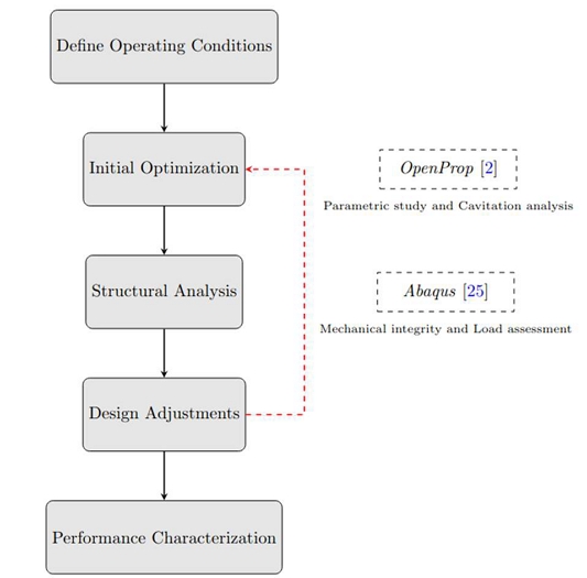
Propeller design methodology overview
2.3 Operating Regime
To ensure optimal performance, it is essential to define the operating regime of the propeller based on the intended conditions. This involves determining the parameters for initial design and optimization: required thrust, ship speed, hub diameter, motor speed and engine power. The optimal performance in this study assumes that the solar boat is in an endurance competition. The first step in this process was analyzing the Drag vs. Ship Speed behavior of the solar boat, presented in Figure 2. The Drag vs. Ship Speed curve was obtained from hull resistance data obtained with a pre-existing in-house computational study performed by FAST team, with the hydrofoil forces numerically evaluated using and in-house MATLAB code.
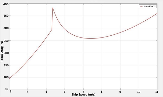
Drag coefficient versus solar boat speed characteristic curve
From the drag behaviour, it is observed that the efficiency of the system is maximised when the ratio of useful work (thrust) to input power is highest. This occurs where the drag is lowest relative to speed, avoiding regions with abrupt increases in drag resistance. The required propeller thrust must, therefore, at least match the total drag at the chosen operating point.
Analysis of the characteristic drag curve in Figure 2 confirms that this theory is consistent with the hydrodynamics of a planing hull. The initial increase in drag at low velocity is driven by the growth of residuary (wavemaking) drag as the solar boat is in displacement mode. The pronounced peak at approximately 5.3 m/s represents the hump speed, where this wavemaking drag is maximised during the energetically costly transition from displacement to planing mode. Conversely, the local minimum at 7.2 m/s indicates a highly efficient pre-planing state, where the vessel operates with a minimised wetted surface area and reduced residuary drag, establishing an optimal balance between speed and power requirement. The subsequent rise in drag at higher velocities is due to the dominance of frictional drag, which increases with speed once the solar boat hull is fully planing and the wetted area stabilises.
Consequently, the values of 260 N for the required thrust and 7.2 m/s for the solar boat endurance speed were selected as the propeller design point. This strategy targets the most efficient operational regime of the hull, directly supporting the overarching goal of maximising endurance for solar-powered racing.
To proceed with the parametric study, the range of a number of blades, rotation speed, and rotor diameter must be defined. At first, high values of rotor diameter were chosen, which led to efficiency around zero. After trying to modify different parameters, it was found that the problem was the rotor diameter range, which was above the appropriate range. Hence, the range was reduced to 10-600mm. The range for the number of blades was 2-5 and the rotation speed was 2000 - 10000 RPM.
An analysis with several different hub diameters was also performed, and the conclusion obtained based on the results was that excessively high RPMs reduce efficiency, and too low RPM results in excessive torque requirements. In order to obtain a balance between the motor efficiency and the propeller efficiency, focusing on obtaining the highest net efficiency, the rotation speed range was shortened to 2000 - 3500 RPM, the propeller diameter adjusted to 20 - 40mm and the number of blades to 2 - 4 blades. These values for RPM were set based on an interpretation of the Dyno Tested Data of the D85L134 Waterproof Brushless Motor specified by FAST, as shown in Table 1, with particular attention to the maximum available torque.

Dyno-Tested Data of D85L134 Waterproof Brushless Motor [26]
From the results for values of hub diameter of both 20 and 50mm, the propeller diameter with the highest efficiency that covers a good range of rotation speed values is next to 0.2m, as seen in Figure 3. In the subsequent single-design optimization, the hub diameter was fixed at 0.05m (50 mm), and the propeller diameter was refined to 0.22m (220 mm); these values are used consistently in the final design and structural analysis. The anomalies observed in the efficiency curves for propeller diameters greater than 0.36 m, particularly the abrupt drops and oscillations, are attributed to limitations in the OpenProp [2] panel-based solver when operating outside typical design boundaries. As the diameter increases, blade area and solidity rise substantially, often pushing the design into hydrodynamically unstable regions where assumptions about inflow conditions, angle of attack, and cavitation behavior may no longer hold. These effects can cause non-convergent or nonphysical results in the numerical model [27]. Additionally, excessively large diameters for a given RPM may produce unrealistic advance ratios, further contributing to the degradation of predicted efficiency. Such numerical issues are a known limitation in blade element momentum theory and related computational models when operating at the edge of their validated parameter space [1][22].
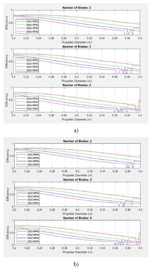
Drag coefficient versus solar boat speed characteristic curve Parametric analysis of propeller efficiency vs. rotational speed for hub diameter: a) 20mm and b) 50mm
Then, the values chosen to begin the study were: number of blades, 2; rotation speed (RPM), 2000; rotor diameter (mm), 200; and hub diameter (mm), 20. For this prototype, a 2-blade propeller configuration was selected over a 3-blade design. This decision was supported by the data presented in Figure 3, which shows that, under similar operating conditions, a 2-blade propeller achieves slightly higher open-water efficiency compared to a 3-blade alternative. In addition to this performance advantage, a 2-blade propeller offers lower drag and reduced rotational resistance, maximising efficiency and minimising inertial loads on the drivetrain. While 3-blade configurations typically provide smoother torque delivery and reduced vibration, the performance gains and simplicity of a 2-blade design made it the more suitable choice for the first prototype, especially in the context of optimising for efficiency.
Finally, it is worth noticing an important parameter to be defined, namely the propeller diameter increment. The increment parameter defines the step size between values in a parametric study; a smaller increment results in a finer resolution, offering more detailed insights but requiring additional computational time. Conversely, a larger increment provides a broader overview with reduced precision. For the following analysis, the propeller diameter increment ratio was defined as , a value reference in blade element momentum theory [1, 22].
2.4 Hydrodynamic Optimization
This section presents the initial optimization phase, during which geometric adjustments were conducted to enhance the performance of the solar-boat propeller. As starting point, an initial geometric configuration was obtained, based on previous FAST information and by fine-tuning parameters such as rotational speed and rotor diameter. In the performance analysis for this initial design, an open-water efficiency of 0.80312 and a torque of 9.893Nm were achieved at a rotation speed of 2250 RPM and a rotor diameter of 220mm. The torque obtained was within the very limits of the maximum available torque values, so the objective would be to decrease this parameter and increase the propeller efficiency, by changing some input values. The hydrodynamic optimization was conducted using OpenProp [2], employing lifting-line theory to model blade performance. Parametric studies adjusted chord length (c/D) and thickness (t0/D) distributions to maximize efficiency and minimize cavitation for a reference configuration with 220mm diameter, 50mm hub, and 2250 RPM, corresponding to the design point later used in the cavitation and structural analyses. An optimized chord distribution should enhance efficiency, reduce cavitation, improve load distribution, and maintain structural integrity. Proper adjustments prevent excessive drag and torque demands. Chord corrections, inspired by Jadmiko et al. [17], yielded c/D = [0.07, 0.09, 0.1045, 0.113, 0.1129, 0.1081, 0.0968, 0.075, 0.0558, 0.01]. Figure 4 show a clear difference between the model before and after the chord length correction. The y-axis represents the chord per radius ratio, and the x-axis represents the radius ratio.
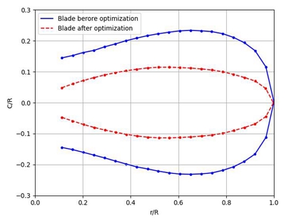
Optimized radial distributions of chord length
The second adjustment made was the blade thickness. Blade thickness affects the structural strength, hydrodynamic performance, and cavitation resistance. One point worth noticing is the thickness of the blade tip should not be smaller than 3 mm, otherwise it would compromise the structural integrity. Thickness was set to t/D =[0.025, 0.022, 0.019, 0.0175, 0.016, 0.0145, 0.013, 0.0115, 0.01, 0], ensuring a minimum tip thickness of 3 mm. Figure 5 present the difference between the model before and after the thickness correction. The y-axis represents the thickness per diameter ratio, and the x-axis represents the radius ratio.
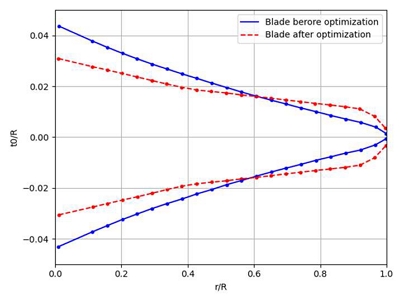
Optimized radial distributions of blade thickness
After implementing the geometry corrections, the performance analysis was conducted once again. The output indicated a significant improvement in efficiency, which increased to 0.84306 (4̃.44% increase, due to geometric optimization). At the same time, torque slightly decreased to 9.424 Nm, and the corresponding shaft power output was 2220.77 W.
2.5 Cavitation Analysis
The next step was the cavitation analysis. A good propeller must present a good balance between cavitation likelihood along the blade and efficiency. In an ideal world, the best propeller would have the highest efficiency and the lowest cavitation probability (if only these two factors were taken into consideration), but these parameters cannot be matched at the same time.
Cavitation was analyzed by assessing pressure distributions via the cavitation number [1]:
| (11) |
and the pressure coefficient, Cp, a dimensionless number that represents the local pressure relative to the dynamic pressure of the flow, defined as:
| (12) |
where p is the local pressure, p∞ is the free stream pressure, pv is the vapor pressure of water, and V is the local flow velocity.
Initial results showed cavitation at the leading edge and mid-chord, as observed in Figures 6 and 7, showing the likelihood of cavitation occurring along the blade at the suction and pressure sides. In Figure 6, the x-axis represents the normalized radial position (r/R) along the blade, and the y-axis represents the normalized chord length (c/R), showing the blade cross-section. The color scale represents Cp/σ , a dimensionless parameter, which serves as an indicator of cavitation susceptibility at different blade sections. Higher values indicate regions where pressure is close to or below the vapor pressure, meaning higher cavitation risk. Lower values indicate higher pressure, meaning less cavitation risk. In order to quantify the risk of cavitation we also present Figure 7 a cavitation map in which the blade is divided into sections with a different coloring scheme, and the y-axis represents the normalized chord length relative to the diameter (c/D). Green shows areas where cavitation will not occur, whereas red shows areas where cavitation will occur and also affect the hydrodynamic properties of the propeller.
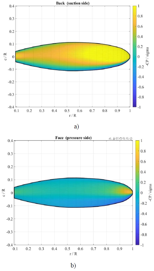
Cavitation analysis showing distribution: a) suction side and b) pressure side
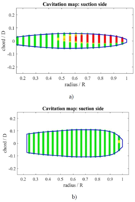
Cavitation map for risk assessment on the suction side: a) before and b) after optimization
There is a clear concentration of cavitation risk near regions from r/R around 0.6 to 1.0 (as reported in Figure 7 b), indicating intense cavitation risk in the outer half of the blade. This pattern suggests localized low-pressure zones on the suction side in that region, likely leading to vapor bubble formation. From a design perspective the reasons for these cavitation risk results are connected with the sharp decrease in the chord length at the blade tip. The blade loses surface area sharply beyond r/R=0.6-0.7, which leads to high pressure gradients and low surface pressures. Another explanation is due to the tip loading, since with reduced chord in the outer section, where thrust is higher due to higher velocity, the blade becomes overloaded, leading to local suction peaks.
These problems can be mitigated by increasing the chord length, mainly at mid-span, for better thrust and cavitation resistance, improving the load distribution and reducing cavitation. Also, to minimize tip vortex cavitation, the chord length near the tip could be reduced. After modifying the chord-diameter ratio of the propeller blade and proceeding to a new cavitation analysis, a significant reduction in cavitation risk was achieved. Figures 8 show the new cavitation distribution and cavitation risk map on the suction side. As seen in Figure 8, the yellow area is now smaller and softer, and in Figure 8 a) the red area vanished, being almost completely covered by green color. This implies that the local pressures on the blade surface are now generally above the cavitation threshold for the given operating conditions.
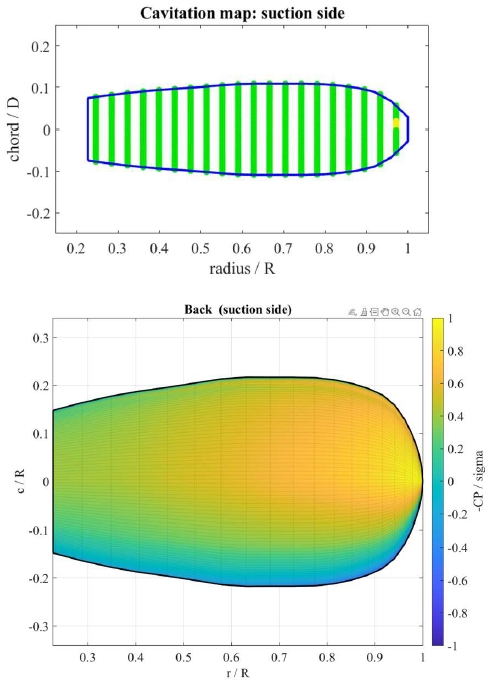
Cavitation map and analysis after geometry corrections on the suction side
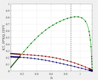
Figure 9 presents the updated open water performance curves for the propeller, displaying the thrust coefficient KT, torque coefficient KQ, and efficiency η as functions of the advance ratio JS. The thrust and torque coefficient curves demonstrate smooth and expected trends, without irregular behavior.
Open-water performance characteristics
Given the operating conditions, the adjustments made to reduce cavitation show characteristic values of a well-optimized marine propeller, with a KT of 0.0789, a KQ of 0.0137, a η of 0.798, a Q of 9.95Nm, and a P of 2345.24W for a JS of 0.873. The efficiency dropped by 5.32% due to cavitation mitigation, when compared to the blade with only the hydrodynamic optimization, staying close to 80%. This represents a good trade-off considering the cavitation enhancement. In the initial hydrodynamic-only configuration, the highest open-water efficiency was obtained close to the original design speed of 2250 RPM. After the cavitation-oriented chord corrections, the efficiency at 2250 RPM decreased slightly, whereas the efficiency in the vicinity of 2000 RPM remained comparatively higher. As a consequence, the final performance curves (Figure 9) exhibit their global maximum at 2000 RPM. This shift reflects the intended compromise between pure open-water efficiency and cavitation risk, rather than a change in the targeted endurance operating regime of the vessel.
2.6 Structural Analysis
This section presents the structural evaluation of the optimized propeller blade, focusing on its mechanical integrity under expected operating loads. The purpose of this analysis is to validate the feasibility of the blade design from a structural standpoint, ensuring that it can withstand hydrodynamic forces without excessive deformation or risk of failure.
A 3D model of the blade was created and analyzed in Abaqus [25] in order to evaluate the mechanical response of the hydrodynamic optimized propeller blade under the defined hydrodynamic loading. The simulation setup included the definition of material properties, loading steps, boundary conditions, pressure load, and mesh configuration.
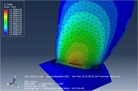
The material assigned to the blade model was an Aluminium Alloy 5083 [19], since is commonly used in marine applications due to its excellent corrosion resistance and high strength-to-weight ratio, and used in previous prototypes by FAST boats. An initial stress concentration study suggested that the stress distribution presented the highest von Mises stress located at the blade root, specifically on the suction side, as observed in Figure 10. The chemical composition of Aluminium 5083 is provided in the Table 2.
Von Mises stress concentration distribution
Chemical composition of Aluminium 5083 [19]
The analysis was configured as a Static, General step. This step type is appropriate for evaluating structural response under constant loading conditions and assumes that inertial and damping effects are negligible. The step includes automatic stabilisation to aid convergence, and it proceeds through a single loading phase without intermediate increments, simulating the steady-state operating condition of the propeller blade.
In order to simulate the hydrodynamic forces acting on the propeller blade, a surface traction load was applied in Abaqus [25]. A total pressure load of 0.02697MPa was obtained by dividing this resultant force of 196.56N from the Thrust (axial force) and the Drag (tangential force) by the blade surface area, Ablade=7286.51mm2). This pressure load was applied uniformly across the entire blade surface, including the fillet region. This reflects the distributed hydrodynamic force experienced by the blade during operation and ensures that stress concentrations at geometric transitions are accurately captured.
To simulate the physical constraint of the blade fixed to the hub, a Displacement/Rotation boundary condition was applied to the hub base. All translational and rotational degrees of freedom were set to zero, fully constraining the root of the model. This reflects a rigid connection, where the blade does not move relative to the fixed portion of the hub. A structured mesh was generated using tetrahedral solid elements, selected for their ability to conform to complex geometries such as the propeller blade and hub connection.
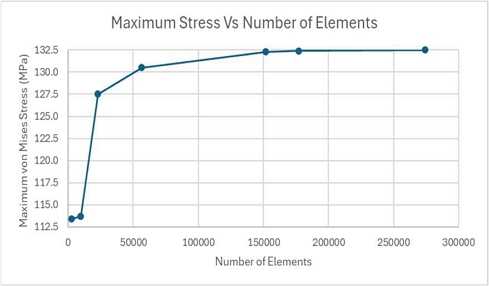
To ensure the accuracy of the stress results and validate the integrity of the model, a mesh convergence study was also conducted, with the results presented in Figure 11.
Maximum Stress vs. Number of Elements
This involved generating multiple refined meshes and comparing the resulting peak stress values. The objective was to identify the point at which further mesh refinement produces negligible variation in results, thus confirming convergence and error assessment. The convergence study, presented in Figure 11, demonstrate that the maximum von Mises stress increases notably during the initial mesh refinements, but begins to plateau beyond approximately 150000 elements. Specifically, the simulation with 151730 elements produced a stress of 132.3 MPa, while the simulation with 177150 elements yielded 132.4 MPa — a difference of only 0.1 MPa, corresponding to a relative variation of less than 0.1%.
The propeller blade, manufactured from Aluminium Alloy 5083 with a yield strength of 228 MPa, demonstrates safe operation under static loading conditions, with von Mises stresses remaining well below the yield limit of the material. However, when fatigue behavior is considered, a more conservative evaluation is necessary. Typical high-cycle fatigue strengths for Al 5083 range from 85 MPa to 135 MPa, depending on factors such as temper condition, loading ratio, and service environment [20, 28]. For example, in the 5083-H111 condition, a fatigue strength of 125 MPa has been reported at room temperature under laboratory conditions [20].
Stress concentration analysis identified the blade-root fillet on the suction side as the critical region, where geometric discontinuities create significant stress concentration (Figure 10). These discontinuities are often the origin of fatigue failures in rotating components subjected to cyclic loads [30]. The fillet radius plays a critical role in moderating stress concentration. According to design literature, increasing the fillet radius can significantly reduce the Stress Concentration Factor (SCF). Peterson [29] studies show that doubling the fillet radius may reduce the SCF by up to 50%, depending on the geometry and type of loading.
To assess the influence of the fillet radius on stress concentration at the blade-hub junction, a parametric study was conducted using three different models with fillet radii of 1 mm, 2 mm, and 4 mm. The objective was to evaluate the effect of this geometric feature on the maximum von Mises stress, taking into account that the fillet region is a critical location for fatigue crack initiation due to its curvature-induced stress amplification [30].
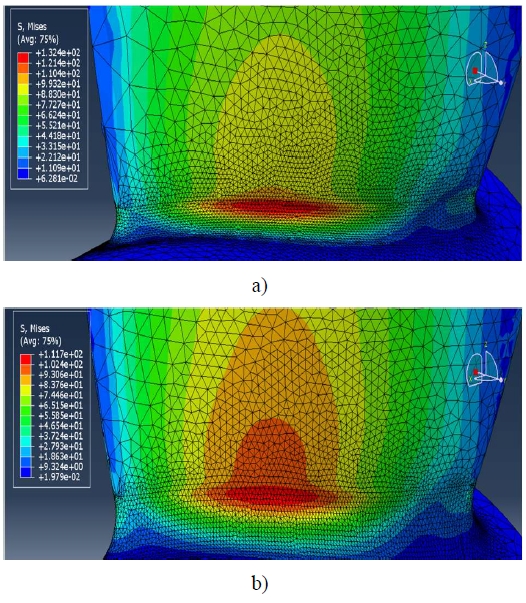
In the result, the 1 mm fillet produced concerning stress levels of 161.2 MPa, substantially exceeding the material’s fatigue limits. In contrast, the 4 mm fillet configuration reduced peak stresses to 117.7 MPa, comfortably below the fatigue threshold while maintaining geometric practicality. This optimal configuration provides a 27% reduction in peak stress compared to the 1 mm design, significantly improving the fatigue resistance of the blade. This reduction is further supported by the stress distribution contours shown in Figure 12 b), where the 4 mm fillet model demonstrates a smoother, more diffuse distribution of von Mises stress. The red high-stress region is smaller and remains localized near the base of the fillet. In contrast, the 2 mm fillet model (Figure 12 a)) reveals a broader and more intense concentration of stress. The high-stress zone extends along the fillet and into the root of the blade, with steeper stress gradients and a rougher transition. This behavior reflects a higher stress concentration factor due to the tighter curvature of the 2 mm fillet. These observations align with the numerical results, confirming that the 4 mm fillet radius significantly reduces peak stress and better manages stress distribution at the blade-hub junction, thereby improving fatigue performance.
Stress concentration at blade-hub junction for fillet radius: a) 2mm and b) 4 mm
Table 3 summarizes fillet radius results.
Maximum von Mises Stress for Different Fillet Radii
3. Results and Performance Characterization
The final view of the optimized 3D geometry of the propeller blade, along with the 2D section blade geometries are presented in Figure 13.
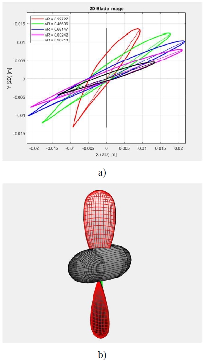
Final propeller geometry (obtained in OpenProp [8]: a) 2d cross section view and b) 3D propeller model
The full performance of the propeller blade was characterized for 1000–8500 RPM, calculating thrust, torque, advance ratio, efficiency, and shaft power using the optimized outputs. This performance is plotted in Figure 14, confirmed stable operation across RPM ranges. Overall efficiency was computed as , with motor data interpolated from Table 1.
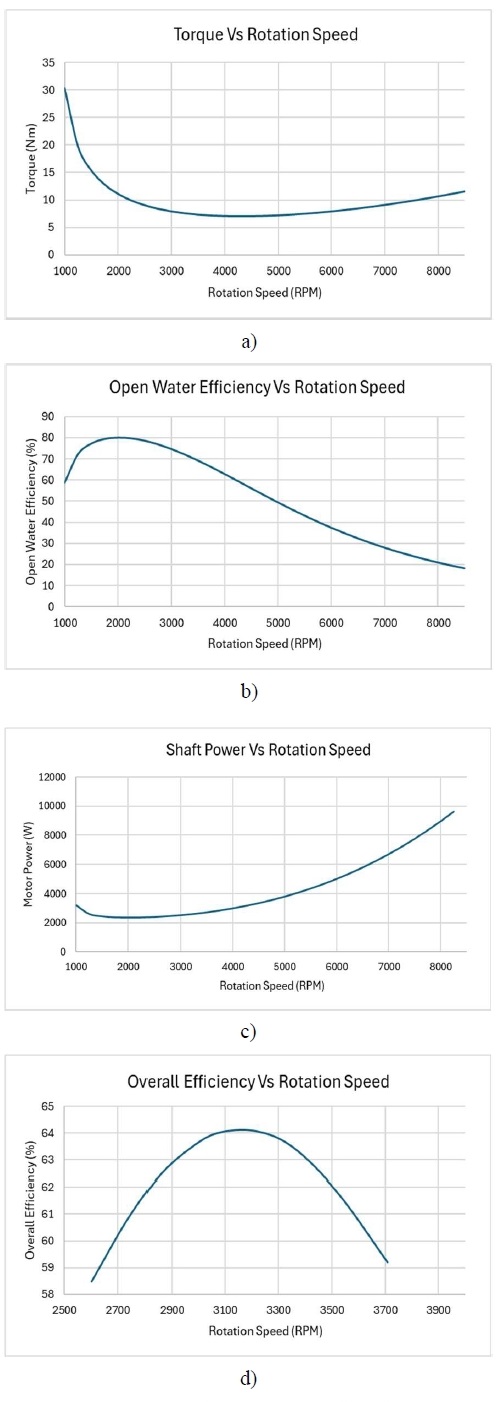
Complete performance characterization curves for the optimized propeller: a) Torque vs. RPM, b) Open-water efficiency vs. RPM, c) Shaft power vs. RPM curve and c) Overall efficiency vs. RPM Final propeller geometry (obtained in OpenProp [8]: a) 2d cross section view and b) 3D propeller model
The optimized propeller, with a 220 mm diameter and 50 mm hub, and two blades, achieved a peak open-water efficiency of 0.8018 at 2000 RPM, delivering 260 N thrust, 11.15 N·m torque, an advance ratio of 0.9818, KT of 0.0999, KQ of 0.0195, and 2334.72 W shaft power. At 3072 RPM, overall system efficiency was 0.6402, with a torque of 7.8656 N m within motor limits (9.278 N m).
To place these results in context, Jadmiko et al. [17] report, for a 320mm three-bladed symmetrical propeller designed for the Jalapatih 3 solar boat, maximum open-water efficiencies of approximately 0.83 (OpenProp) and 0.84 (CFD) at an advance ratio of J ≈ 1.4, with thrust and torque coefficients on the order of KT ≈ 1.4 and KQ ≈ 0.037. The present propeller, with η0=0.8018 at Jj=0.9818, KT ≈ 0.0999 and KQ=0.0195, therefore lies in a similar high-efficiency range while targeting a smaller, two-bladed, 220mm diameter configuration tailored to the FAST hull and power constraints. The two-blade configuration minimized drag and inertial loads, optimizing performance for solar-powered operation. Geometry adjustments, particularly increased mid-span chord and hub diameter, effectively reduced cavitation, though minor risks at higher RPMs warrant further CFD analysis [18]. Structural analysis showed a maximum von Mises stress of 117.7 MPa with a 4 mm fillet, below the 125 MPa fatigue limit of Aluminium 5083-H111 [20]. The 4 mm fillet radius reduced stress concentration by 26.99% compared to 1 mm, ensuring fatigue resistance, though proximity to the fatigue limit suggests potential for material upgrades (e.g., composites) [1]. Aluminium 5083-H111 was selected for its corrosion resistance and lightweight properties (and because it is used in the experimental prototype in FAST solar-boat), but its fatigue strength (125 MPa) limits long-term durability under variable marine conditions [20]. Cavitation analysis post-optimization (Figure 8) showed negligible risk, with smooth pressure distributions. OpenProp [2] limitations, such as simplified cavitation modeling, highlight the need for CFD or experimental validation [27]. Therefore, the hydrodynamic and cavitation predictions presented in this paper should be interpreted as first-order design estimates based on a lifting-line panel method. The absence of CFD-based validation is recognised as a key limitation of the current study and is mainly due to the scope and time constraints of the original semester project: within the report deadline, it was not feasible to both learn and validate a new CFD workflow while also completing the propeller design, optimization, and structural analysis tasks. A dedicated CFD campaign (and, where possible, experimental testing of a manufactured prototype) is identified as priority future work to quantitatively validate and refine the propeller performance and loading predictions.
Finally, it is important to note that the initial design point used to define the operating conditions and structural load case was 2250 RPM, whereas the performance curves of the optimized geometry reveal that the highest open-water efficiency is achieved at 2000 RPM. For this reason, both operating points are reported in this work: 2250 RPM as the nominal endurance design condition used in the cavitation and structural analyses, and 2000 RPM as the hydrodynamically optimal operating regime of the final propeller.
4. Conclusion
The main objective of this project was to design, optimise, and validate a marine propeller tailored for FAST first solar-powered vessel. The results obtained successfully meet the performance, structural, and efficiency targets initially established. The final propeller geometry was defined with two blades, a diameter of 220 mm, a hub diameter of 50 mm, and a rotational speed of 2250 RPM, operating at a vessel speed of 7.2 m/s and generating a required thrust of 260 N. This rotational speed corresponds to the nominal endurance operating condition of the boat, even though the maximum isolated propeller efficiency is obtained at 2000 RPM. From the structural analysis, the final design with a 4 mm fillet radius exhibited a maximum von Mises stress of 117.7 MPa under operational loading conditions. This value is below the conservative fatigue strength limits for 5083 Aluminium alloy, ensuring mechanical integrity under cyclic loads. In terms of hydrodynamic performance, the propeller reached its peak open-water efficiency of 0.8018 at 2000 RPM. This best-efficiency point at 2000 RPM results from the cavitation-mitigation chord redistribution, which slightly reduces the efficiency at the original 2250 RPM design speed in exchange for a much lower cavitation risk. Thus, 2250 RPM is kept as the nominal endurance operating condition of the boat, while 2000 RPM represents the most efficient operating regime of the final, cavitation-corrected propeller geometry. At this operating point, the key performance parameters were: torque (Q) of 11.15 Nm, advance ratio (J) of 0.9818, thrust coefficient (KT) of 0.0999, torque coefficient (KQ) of 0.0195, shaft power of 2334.72 W, and estimated motor power input of 2594.13 W. When combining the motor efficiency with the propeller efficiency, the highest overall system efficiency was achieved at 3072 RPM, reaching a value of 0.6402. This comprehensive characterization demonstrates the effectiveness of the design process and provides critical data for control system integration and energy management.
Nomenclature
| AUV : | Autonomous Underwater Vehicle |
| CFD : | Computational Fluid Dynamics |
| FEUP : | Faculdade de Engenharia, Universidade do Porto |
| FAST : | FEUP Academic Solar Team |
| MIT : | Massachusetts Institute of Technology |
| ML : | Machine learning |
| RPM : | Revolutions per minute |
| SCF : | Stress Concentration Factor |
Acknowledgments
Paulo Silva acknowledges FEUP Academic Solar Team (FAST) and, especially, its member Sebastião Mendonça for the continuous support during the project. A. M. Afonso acknowledges FCT - Fundação para a Ciência e a Tecnologia for financial support through LA/P/0045 (ALiCE, Associate Laboratory in Chemical Engineering), UIDB/00532 and UIDP/00532 (CEFT, Transport Phenomena Research Center) funded by national funds through FCT - Fundação para a Ciência e a Tecnologia.
Author Contributions
Conceptualization, P. Silva and A. Afonso; Methodology, P. Silva and A. Afonso; Software, P. Silva and A. Afonso; Formal Analysis, P. Silva and A. Afonso; Investigation, P. Silva and A. Afonso; Resources, P. Silva and A. Afonso; Data Curation P. Silva; Writing-Original Draft Preparation, P. Silva and A. Afonso; Writing-Review Editing,P. Silva and A. Afonso; Visualization, P. Silva and A. Afonso; Supervision, A. Afonso; Project Administration, A. Afonso; Funding Acquisition, A. Afonso.
References
-
J. S. Carlton, Marine Propellers and Propulsion, 2nd ed., Butterworth-Heinemann, 2007.
[https://doi.org/10.1016/B978-075068150-6/50012-7]

-
B. P. Epps, M. J. Stanway, and R. W. Kimball, “Open-prop: an open-source design tool for propellers and turbines,” SNAME Propellers and Shafting Symposium, Williamsburg, VA, 2009. Available:
[https://doi.org/10.5957/PSS-2009-09]
- J. Bosschers, PROCAL v2.0 Theory Manual, MARIN Report No. 20834-7-RD; MARIN: Wageningen, The Netherlands, 2009.
- Cooperative Research Ships. Available at: http://www.crships.org, .
-
S. Kinnas, “A general theory for the coupling between thickness and loading for wings and propellers,” Journal of Ship Re-search, vol. 36, pp. 59-68, 1992.
[https://doi.org/10.5957/jsr.1992.36.1.59]
- J. Kerwin, S. Kinnas, and M. B. Wilson, “Experimental and analytical techniques for the study of unsteady propeller sheet cavitation,” Proceedings of the 16th Symposium on Naval Hy-drodynamics, pp. 387–414, 1986.
-
S. A. Kinnas, H. Lee, and Y.L. Young, “Modeling of Unsteady Sheet Cavitation on Marine Propeller Blades,” Interna-tional, Journal of Rotating Machinery, vol. 9, pp. 263–277, 2003.
[https://doi.org/10.1155/S1023621X03000241]
- B. Epps, J. Chalfant, R. Kimball, A. Techet, K. Flood, C. Chryssostomidis, “OpenProp: An open-source parametric design and analysis tool for propellers,” Proceedings of the 2009 Grand Challenges in Modeling & Simulation Conference, pp. 104–111, 2009.
-
K. P. D’Epagnier, H. L. Chung, M. J. Stanway, R. W. Kimball, “An open source parametric propeller design tool,” Oceans 2007, pp. 1-8, 2007.
[https://doi.org/10.1109/OCEANS.2007.4449400]
-
J. G. Bellingham, Y. Zhang, J. Kerwin, et al., (2010). Efficient propulsion for the Tethys long-range autonomous underwa-ter vehicle, 2010 IEEE/OES Autonomous Underwater Vehicles, IEEE, 2010.
[https://doi.org/10.1109/AUV.2010.5779645]
- Z. Li and Y. H. Wang, “Autonomous underwater vehicle appearance and propulsion system optimization design,” Journal of Machine Design, vol. 34, no. 5, pp. 23–29, 2017 (in Chinese).
-
W. Zhang, L. Wu, X. Jiang, X. Feng, Y. Li, J. Zeng and C. Liu, “Propeller design for an autonomous underwater vehicle by the lifting-line method based on OpenProp and CFD,” Journal of Marine Science and Application, vol. 21, no. 2, pp. 106-114, 2022.
[https://doi.org/10.1007/s11804-022-00275-w]
-
K. J. Lee, H. Tetsuji, J. H. Lee, “A lifting surface optimization method for the design of marine propeller blades,” Ocean Engineering, vol. 88, pp. 472–479, 2014. Available:
[https://doi.org/10.1016/j.oceaneng.2014.07.010]
-
G. Stefano, J. Gonzalez-Adalid, M. P. Sobrino, “Design and analysis of a new generation of CLT propellers,” Applied Ocean Research, vol. 59, pp. 424–450, 2016. Available:
[https://doi.org/10.1016/j.apor.2016.06.014]
-
C. Wang, K. Han, C. Sun, C. Y. Guo, “Marine propeller optimization design and parameter analysis,” J. Huazhong Univ. of Sci. & Tech. (Natural Science Edition), vol. 48, no. 4, pp. 97–102, 2020. Available:
[https://doi.org/10.13245/j.hust.200418]
-
H. Vardhan, N. Kumari, P. Volgyesi, and J. Sztipanovits, “Fusion of ML with numerical simulation for optimized propeller design,” 2024 IEEE Workshop on Design Automation for CPS and IoT (DESTION), pp. 22-27, 2024. Available:
[https://doi.org/10.1109/DESTION62938.2024.00010]
-
E. Jadmiko, T. B. Musriyadi, and A. S. Akram, “Analysis Symmetrical Blade Propeller Performance for Jalapatih 3 Ship Using CFD,” International Journal of Marine Engineering Innovation and Research, vol. 5, no. 4, pp. 216–223, 2020.
[https://doi.org/10.12962/j25481479.v5i4.7630]
- J. Alegre, “Design e analise a Cavitacao dos Helices do SR03,” Internal technical report, FAST team, 2022.
- thyssenkrupp Materials (UK), 2020. “Aluminium Alloy 5083-O / H111 – Technical Datasheet.” Available at: https://ucpcdn.thyssenkrupp.com/_legacy/UCPthyssenkruppBAMXUK/assets.files/material-data-sheets/aluminium/5083-o-h111.pdf, .
- H. Zhang, et al., “Fatigue Behavior of Aluminum Alloy 5083-H111 at Various Temperatures,” Materials, vol. 14, no. 6, p. 1472, 2021.
- R. G. Budynas and J. K. Nisbett, Shigley’s Mechanical Engineering Design, 10th ed. McGraw-Hill Education, 2014.
-
J. P. Breslin and P. Andersen, Hydrodynamics of Ship Propellers, Cambridge University Press, 1994.
[https://doi.org/10.1017/CBO9780511624254]
-
D. B. Preso, D. Fuster, and A. B. Sieber, D. Obreschkow, and M. Farhat, “Vapor compression and energy dissipation in a collapsing laser-induced bubble,” Physics of Fluids, vol. 36, no. 3, 2024. Available:
[https://doi.org/10.1063/5.0200361]
-
A. M. Zhang, S. M. Li, R. Z. Xu, and S. C. Pei, S. Li, and Y. L. Liu, “A theoretical model for compressible bubble dynam-ics considering phase transition and migration,” Journal of Fluid Mechanics, no. 999, p. A58, 2024. Available:
[https://doi.org/10.1017/jfm.2024.954]
- M. Smith, ABAQUS/Standard User’s Manual, Version 6.9., United States: Dassault Systemes Simulia Corp; 2009.
- Hobiba, 2025. “D85L134 Waterproof Brushless Motor 12kW.” Available at: https://en.hobiba.cn/Products_details/D85L134-Waterproof-Brushless-Motor-12kw, .
- C. Gkiokas, Marine propellers optimization with the use of software OpenProp, Massachusetts Institute of Technology, United of the States, 2022. Available: https://web.mit.edu/2.29/www/img/projects/spring_2022/Chris.pdf, .
-
Song, C.-R., Zhang, S.-Y., Liu, L., Yang, H.-Y., Kang, J., Meng, J., Luo, C.-J., Wang, C.-G., Cao, K., Qiao, J., Shu, S.-L., Zhu, M., Qiu, F., & Jiang, Q.-C. (2024). Research Progress on the Microstructure Evolution Mechanisms of Al-Mg Alloys by Severe Plastic Deformation. Materials, vol. 17, no. 17, p. 4235, 2024. Available:
[https://doi.org/10.3390/ma17174235]
- R. E. Peterson, Stress Concentration Factors, John Wiley & Sons, 1959, 978-0471671683.
- R. G. Budynas and J. Keith Nisbett, Shigley’s Mechanical Engineering Design,10th, McGraw-Hill Education, 2014, 978-0073398204.