
Recent progress in hydrogen-fueled direct injection spark ignition engines: Review of technologies for power enhancement and NOₓ emission reduction
Copyright © The Korean Society of Marine Engineering
This is an Open Access article distributed under the terms of the Creative Commons Attribution Non-Commercial License (http://creativecommons.org/licenses/by-nc/3.0), which permits unrestricted non-commercial use, distribution, and reproduction in any medium, provided the original work is properly cited.
Abstract
The decarbonization of the maritime sector has intensified interest in hydrogen-fueled internal combustion engines as a viable alternative to conventional powertrains. This review synthesizes current research by linking the fundamental properties and combustion characteristics of hydrogen to recent advancements in direct injection technologies. Although hydrogen enables carbon-free combustion and offers favorable properties such as high diffusivity and a wide flammability range, its low density and high combustion temperature impose inherent limitations, including low power density and elevated NOₓ emissions. In response, DI-based approaches combined with injection optimization, boosting, and water injection have significantly improved engine performance. However, further progress is increasingly constrained by combustion-related phenomena, particularly knock, rapid flame development, and mixture inhomogeneity under high-load conditions. At the same time, strategies for NOₓ reduction, such as lean operation and advanced injection techniques, remain limited by combustion instability and an incomplete understanding of in-cylinder mixture formation. These limitations are further compounded by the lack of integrated experimental and computational studies, which restricts the development of generalized design guidelines. By systematically integrating these findings, this review provides a comprehensive framework for understanding the interrelated challenges of direct-injection hydrogen internal combustion engines and offers guidance for the development of high-power-density and low-NOₓ-emission hydrogen engines.
Keywords:
Hydrogen direct injection spark ignition engine, Abnormal combustion, Power enhancement, NOₓ emissions1. Introduction
Energy-related carbon dioxide (CO2) emissions reached 37.8 Gt in 2024, the greatest amount in history [1]. While this figure indicates an increase of 0.4 Gt compared to that in 2023—contradicting the global commitment to reducing CO₂ emissions—clean energy sources such as solar photovoltaics, nuclear power, and electricity have proven their effectiveness by preventing an estimated 2.6 Gt of energy-related CO₂ emissions annually [1][2].
Given the urgent need for clean energy adoption, 99% of the 125 trillion ton-kilometers of international shipping activity in 2022 relied on fossil fuels, resulting in the emission of 0.89 Gt of CO₂ [3][4].
These findings highlight the critical role that clean energy technologies could play in rapidly and substantially reducing emissions in the global transport sector.
To reduce CO₂ emissions in the shipping sector, increasing attention is being given to clean energy sources such as bioenergy, hydrogen (H2), and H2-based fuels. In particular, the International Energy Agency (IEA) projects that the share of shipping activity powered by H2 fuels will increase to 19% by 2050. Moreover, H2 bunkering technologies for vessels are expected to achieve market uptake by 2027 [3].
H2-powered powertrains can be classified into H2 fuel cells (FCs) and H2 internal combustion engines (ICEs). H2-FCs generate electricity through an electrochemical reaction between H2 and oxygen (O2) and have advantages such as higher efficiency and zero emissions compared with ICEs. However, H2-FCs also have several drawbacks, including high costs, limited durability, and the requirement for high-purity H2 [5]-[7].
H₂-ICEs have advantages such as lower cost, higher durability, a longer lifespan, and the ability to leverage numerous technologies accumulated through long-term research on conventional ICEs [8][9]. Moreover, because no CO₂ emissions are produced during the combustion process, H₂-ICEs are considered promising powertrains for H2-powered ships [5], [10], [11].
Owing to these advantages, extensive research has been conducted on H2-ICEs for ships. For example, El-Gohary [12] designed a marine H2-ICE using a computer program and compared its performance with that of a conventional medium-speed diesel engine. The results revealed that compared with the diesel engine, the H₂-ICE had lower thermal efficiency and brake mean effective pressure (BMEP). Moreover, larger engine dimensions were necessary for the H₂-ICE to achieve a power output comparable to that of the diesel engine.
Additionally, Seddiek et al. [10] pointed out the lower power density of hydrogen engines, as compared to conventional ICEs and reported that technologies such as intake pressure boosting and direct injection technologies have been investigated to address this limitation for marine applications. Moreover, through a life cycle assessment, Ventayol et al. [5] demonstrated that H2-ICEs outperform H2-FCs in shipping applications in terms of global warming potential and abiotic depletion potential.
Despite ongoing efforts by researchers, few studies have focused on H2-ICE technologies for marine applications. Accordingly, this study provides insights into H2-ICE technologies by evaluating the current state of knowledge to accelerate research and development in the maritime sector.
Specifically, this study compares the characteristics of H2 as an engine fuel with those of conventional fossil fuels. Based on this comparison, the advantages and disadvantages of H2-ICEs are discussed, highlighting the unique properties of hydrogen. The analysis indicates that, while hydrogen is a promising fuel for internal combustion engines because of its favorable combustion characteristics and carbon-free nature, it also introduces critical challenges, including abnormal combustion phenomena, reduced power output, and high NOₓ emissions. Furthermore, to address these limitations, recent experimental and numerical studies were carefully selected and systematically reviewed. Their findings were critically examined to identify how each approach contributes to overcoming the inherent limitations of hydrogen engines, and the implications of these studies were synthesized from an academic perspective.
2. Literature Selection Methodology
To enhance the rigor and comprehensiveness of this review, a structured approach was adopted for the selection of relevant literature on H2-ICEs.
First, a comprehensive literature search was conducted using major scientific databases, including Web of Science and Scopus. In addition, technical reports from international organizations, as well as conference proceedings and academic theses, were also considered to ensure broad and up-to-date coverage of the field. The primary focus was placed on studies published between 2000 and 2025, while earlier foundational works were included where necessary to provide fundamental insights into H2 combustion characteristics.
Second, the identified studies were screened based on predefined selection criteria. Peer-reviewed journal articles were prioritized. Moreover, high-quality conference papers and relevant academic theses were also included when they provided significant experimental or numerical insights not widely available in journal publications. Studies were included if they (i) investigated H2-ICEs and (ii) presented experimentally validated or numerically supported analyses of engine performance, combustion characteristics, or emissions.
Third, the selected literature was further evaluated in terms of technical relevance and contribution. Particular attention was given to studies addressing key challenges of H2-ICEs, including abnormal combustion phenomena, power output limitations, and NOₓ emissions.
Finally, rather than providing a purely descriptive overview, the selected studies were systematically analyzed and compared. Their findings were critically examined to identify common trends, technological limitations, and effective mitigation strategies. Based on this synthesis, key research gaps and future research directions were highlighted to provide a structured and academically rigorous review of H2-ICEs.
3. Hydrogen as an Engine Fuel
3.1 Physical and Chemical Properties of Hydrogen
Because the properties of fuels significantly affect the characteristics of ICEs, extensive research [13]-[15] has been conducted on the properties of H2. These studies have reported both the suitability and the vulnerabilities of H2 as a fuel for ICEs. The selected physical and chemical properties of H2, namely, methanol, and isooctane, adapted from Verhelst and Wallner [14], are shown in Table 1.

Physical and chemical properties of H2, methanol, and isooctane at 300 K and 1 atm. Adapted from Verhelst and Wallner [14].
Owing to its lower molecular weight than methane and isooctane, H2 has a significantly higher mass diffusivity. Because better mixing with air facilitates more efficient combustion reactions, this high mass diffusivity is a major advantage of H2 as an engine fuel [16].
H2 has an extremely low density—approximately 8 times lower than methane and 8,650 times lower than isooctane—resulting in a significantly greater volume requirement for storage. This low density is a major disadvantage in the use of H2 as a fuel, necessitating the implementation of high-pressure or cryogenic storage technologies [10], [14], [15], [17]. Furthermore, the development of high-efficiency H2-ICEs is increasingly emphasized to enable more effective utilization of H2.
Compared with other conventional fuels, H2 has a significantly lower minimum ignition energy, enabling prompt ignition with minimal energy input [15], [18]. However, this characteristic can also result in undesirable phenomena, such as backfire during the intake stroke or pre-ignition during the compression stroke, because of hot spots or residual gases in the engine [18]-[20].
The flammability limit of H2 has a significant effect on the operation of H2ICEs. Owing to its wide flammability range, H2 allows engine operation over a wide range of air–fuel ratios, resulting in a wide operating range of power output [15]. Notably, H2 becomes flammable at concentrations as low as 4 vol% in air, enabling unthrottled operation that avoids throttle losses [15], [18].
For example, Kim reported that engine operation at λ = 3.0 was achievable under unthrottled conditions by controlling the injected mass of H2 [9].
Moreover, the lower flammability limit of H2 facilitates the application of lean burn strategies, which helps reduce combustion temperature, thereby reducing heat transfer losses and suppressing the formation of nitrogen oxide (NOₓ) [14], [15], [18]. However, this characteristic, when combined with the low minimum ignition energy of hydrogen, also increases the risk of abnormal combustion, which refers to unintended combustion phenomena, such as knock, pre-ignition, and backfire, that deviate from normal spark-initiated combustion in the engine [14], [15], [18].
Although H₂ has a higher lower heating value (LHV) than methane or isooctane, its low density results in a significantly lower volumetric energy content than that of the other fuels. According to Stępień, under conditions of 0.1 MPa and 273 K, the volumetric energy contents of methane and isooctane are 33 MJ/m³ and 33,000 MJ/m³, respectively, whereas that of H2 is only 10.7 MJ/m³ [18].
This characteristic, combined with the high stoichiometric air-to-fuel ratio of hydrogen (34.2), necessitates a larger volume of air for combustion, which contributes to the relatively low power output of H2 engines compared with that of conventional engines [14], [18], [21].
In particular, Kumar [21] reported that owing to these limitations, the theoretical output of an H2-engine using port fuel injection (PFI) is only approximately 85% of that of a gasoline engine. To address this issue, researchers have proposed the use of direct injection (DI) technology, in which the combustion chamber is first filled with air before H₂ is directly injected into the cylinder [10], [14], [15], [18], [21]. In contrast to the PFI system, in which a premixed air–fuel mixture is inducted, the DI system allows a greater mass of air to be introduced into the cylinder. Consequently, a larger quantity of H₂ can be injected, leading to enhanced engine output. With this approach, the theoretical power output of a DI H2 engine can exceed that of a PFI gasoline engine [14], [18], [21].
In summary, the physical and chemical properties of H2 imply several key considerations. First, the low density of H2 necessitates the development of advanced storage technologies and high-efficiency engine systems for its practical use as an engine fuel. Second, abnormal combustion induced by its low minimum ignition energy and wide flammability range must be effectively controlled. Third, further research on direct injection (DI) technology is required to address the issue of low power output.
3.2 Combustion Properties of Hydrogen
Because the combustion characteristics of a fuel substantially affect engine design, such as ignition type, compression ratio, and fuel injection type, research on the combustion characteristics of H2 has also been conducted. Table 2 presents the combustion properties of H2, methanol, and isooctane, as reported by Das [15] and Verhelst and Wallner [14].
Combustion properties of H2, methanol, and isooctane at 300 K and 1 atm. Adapted from Das [15] and Verhelst and Wallner [14].
H2 has a higher autoignition temperature than other fuels. Therefore, achieving compression ignition in H2-ICEs requires a high compression ratio design. However, this design involves challenges in controlling the combustion process, increases the risk of knocking, and may cause mechanical damage to the engine [18], [22], [23]. Consequently, it is more appropriate to employ a spark ignition system, in which an electrical spark serves as the ignition sourceto initiate combustion of the air–fuel mixture in H2-ICEs.
The high burning velocity of H2 enables combustion that more closely resembles constant-volume combustion than that of other fuels, thereby approximating the ideal Otto cycle [18]. Notably, several studies have reported that at λ = 2.0, the laminar burning velocity of H2–air mixtures exceeds those of methane–air and isooctane–air mixtures under stoichiometric conditions [14], [24]-[26]. As a result, H2-ICEs can achieve high thermal efficiency even under lean conditions through rapid combustion. However, this high burning velocity, under near-stoichiometric conditions, is associated with a high adiabatic flame temperature, which results in increased NOₓ emissions in H2-ICEs [14].
H2 has a quenching distance of only 0.064 cm, which is significantly smaller than that of other fuels. Owing to this short quenching distance, H₂ flames are more resistant to extinction than flames of other fuels. Consequently, in engines, this characteristic can result in crevice combustion, increased thermal loads on the piston top land, and greater wall heat transfer losses [14], [18], [27].
In summary, the combustion properties of H₂ suggest several important considerations for its application in engines. First, spark ignition is more suitable for H2-ICEs to effectively control the combustion process. Second, strategies are required to mitigate NOx emissions caused by the high combustion temperature of H2. Third, measures are needed to reduce wall heat transfer losses associated with the small quenching distance of H2.
4. Advances in H2-ICEs technologies
As discussed in Section 3, while the properties of hydrogen offer several advantages for H2-ICEs, they also introduce critical limitations that hinder their practical application. These include the low power density, susceptibility to abnormal combustion phenomena, and significant NOₓ emissions under near-stoichiometric conditions.
To address these challenges, extensive research efforts have been conducted, leading to notable technological advancements in H2-ICEs. Accordingly, this section reviews and categorizes recent studies based on their approaches to mitigating these limitations, with a focus on improving engine performance and emission characteristics.
4.1 Transition from External Mixture Formation to Direct Injection in H2-ICEs
Mixture formation methods, broadly classified into external and internal mixture formation, play a critical role in determining the mass of air inducted into the cylinder. As discussed in Section 3, H2 requires a larger amount of air for combustion compared to conventional fuels, which makes the mixture formation strategy a key factor influencing power output. Accordingly, numerous studies have focused on identifying and optimizing mixture formation methods to enhance the power output of H2-ICEs.
External mixture formation methods, such as carburetor injection, intake manifold fuel injection, or PFI, introduce a premixed air–fuel mixture into the cylinder through the intake system. This configuration inherently limits the amount of fresh air that can be inducted, making it difficult to achieve high air mass flow rates. As a result, external mixture formation imposes a fundamental constraint on increasing the power output of H2-ICEs.
In particular, due to the high stoichiometric air–fuel ratio requirement of H2, the volumetric efficiency of H2-ICEs operating with external mixture formation is significantly lower than that of engines fueled with conventional fuels. This reduction in volumetric efficiency is primarily attributed to the displacement of intake air by the premixed fuel. In this regard, Binder and Withalm [28] quantitatively demonstrated that the intake air loss in hydrogen engines using external mixture formation is approximately 30%, whereas that of other fuels, including methane, ethane, propane, and butane, remains below 10%.
To mitigate this reduction in volumetric efficiency, approaches such as supercharging or cryogenic H2 PFI had been investigated [29]-[32]. However, these efforts highlighted the need for a fundamentally different mixture formation strategy capable of overcoming the inherently low volumetric efficiency of external mixture formation methods and the resulting limitations in power output. Consequently, consensus has shifted to the H2 DI, which enables a greater mass of air to be inducted into the cylinder by avoiding premixing in the intake system.
This shift is supported by several studies. Srinivasana and Subramanian [33], Faizal et al. [34], and Stępień [18] reported that42% more power was obtained from H₂ DI than from carburetor injection. Verhelst and Wallner [14] also demonstrated that the theoretical power density of a DI H2-ICE is 33% greater than that of a PFI H2-ICE.
Furthermore, Mohammadi et al. [35] found that H2 injection during a compression stroke results in higher power output than injection during an intake stroke because of the intake valve closing timing. Specifically, injecting fuel at BTDC 130° CA, when the intake valve has closed, had a negligible impact on volumetric efficiency even as the fuel quantity increased. In contrast, injecting fuel at BTDC 300° CA, when the intake valve is still open, led to a rapid decrease in volumetric efficiency with increasing fuel quantity. These findings demonstrate that, even in DI engines, achieving high volumetric efficiency requires careful selection of fuel injection timing with respect to the intake valve closing timing.
Meanwhile, abnormal combustion phenomena, such as pre-ignition and backfire, arising from the low minimum ignition energy of H2, also represent major obstacles to increasing the power output of H2-ICEs employing external mixture formation methods.
Among these abnormal combustion phenomena, pre-ignition is considered one of the most critical issues in H2-ICEs, as it can initiate combustion prior to the intended spark timing and lead to severe deterioration in engine performance. Therefore, understanding the mechanisms of pre-ignition and developing effective mitigation strategies are essential for improving the operability of H2-ICEs.
Pre-ignition refers to the unintended and premature combustion of the air‒fuel mixture during the compression stroke [14], [15], [36]. Because the minimum ignition energy of H2 is extremely low, high temperatures of residual gases, spark plugs, exhaust valves, or lubricants can cause pre-ignition in H2-ICEs [14], [37]-[40]. In particular, pre-ignition is more likely to occur in H2-ICEs with external mixture formation methods because H2 and air are mixed in the intake system and enter the combustion chamber. Moreover, Verhelst and Wallner [14] reported that pre-ignition can reduce the indicated mean effective pressure (IMEP) to approximately 0 MPa because of an early increase in pressure before ignition timing.
To overcome pre-ignition in H2-ICEs with external mixture formation methods, various methods, such as using cold-rated spark plugs, modifying spark plug size, or employing cooled exhaust valves, have been investigated [36], [41], [42]. For example, Furuhama et al. [36] reported that, in an intake-manifold H2-ICE, the use of smaller spark plugs with an increased gap, which facilitates cooling, suppressed pre-ignition and thereby increased the maximum power output by approximately 0.5 PS. However, pre-ignition was still observed as the air–fuel mixture approached stoichiometric conditions or as the engine load increased. These findings indicate that suppressing pre-ignition under high-load conditions is fundamentally difficult in H2-ICEs employing external mixture formation methods.
Backfire, another type of unintended premature combustion, occurs when an H2-air mixture ignites during the intake stroke [14]. Because backfire can cause problems, which range from simple misfires to severe fires in the fuel system [15], the use of H2-ICE with external mixture formation methods under high-load conditions has been limited. For example, Lee et al. [43] reported that the maximum brake mean effective pressure (BMEP) of a PFI H2-ICE was approximately 0.6 MPa at φ = 0.8 and 1000 rpm due to backfire. Furthermore, Yi et al. [44] reported that backfire occurring in the region above φ = 0.7 made it impossible for the PFI H2-ICE to increase its IMEP beyond 0.8 MPa.
To avoid backfire, various methods such as optimizing fuel injection timing, retarding ignition timing, and installing flame arrestors have been investigated. Specifically, Duan et al. [20] reported that optimized H2 injection timing affects backfire control by reducing the local concentration and temperature of the fuel‒air mixture in the inlet port. Additionally, Saravanan et al. [45] reported that the installation of a net-like flame arrestor can extinguish flames propagating from cylinders to the intake manifold. Nevertheless, these approaches have not fundamentally resolved backfire in H2-ICEs with external mixture formation methods and resulted in only minimal improvements in power output. Consequently, research efforts have increasingly shifted toward DI systems, in which H₂ is injected directly into the cylinder.
4.2 Advances in direct injection H2-ICEs for power output enhancement and NOx emission reduction
As discussed in Section 4.1, the DI method fundamentally eliminates abnormal combustion phenomena by preventing fuel from being introduced into the intake system. This inherent advantage has enabled engine operation under high-load operation. Consequently, extensive research efforts have been directed toward enhancing the power output of DI H2-ICEs. In addition, considerable attention has been given to mitigating NOₓ emissions, which tend to increase under high-load conditions. This subsection provides a comprehensive review of these research efforts, with a focus on the effects of DI on power enhancement and NOₓ emission reduction, and discusses implications for future development of H2-ICEs.
First, among the various parameters affecting the performance of DI H2-ICEs, fuel injection timing has been a primary focus in efforts to improve power output [46]-[49]. Rahman et al. [46] demonstrated that owing to the interaction between injection duration and ignition timing, excessively retarded injection timing significantly reduced power output. Specifically, a fuel injection timing of BTDC 60° CA-yielded a power output of 89.38 kW under stoichiometric conditions (φ = 1.0), whereas retarding the injection timing to BTDC 10° CA reduced the power output to less than 60 kW at the same fuel–air equivalence ratio. Additionally, Lee [48] reported that although retarding the fuel injection timing from BTDC 160° CA to BTDC 120° CA resulted in higher thermal efficiency because of mixture stratification, which refers to the non-uniform distribution of the air–fuel mixture within the combustion chamber, typically characterized by locally rich and lean regions, the maximum net indicated mean effective pressure (nIMEP) decreased from 0.82 MPa to 0.71 MPa because of the low injector flow rate and the ignition timing, which was set to achieve maximum brake torque as shown in Figure 1. This phenomenon can be attributed to the use of conventional injectors designed for liquid fuels to inject gaseous H2. While conventional injectors are well suited for high-density liquid fuels, they are not capable of supplying a sufficient mass flow rate of low-density H2 gas. Consequently, it becomes difficult to inject an adequate amount of fuel within the limited time available before ignition timing, during which the in-cylinder pressure rapidly increases.
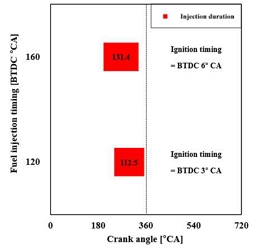
Injection duration and ignition timing for the fuel injection timings of BTDC 160 and 120° CA at the maximum nIMEP. Adapted from Lee [48]
Based on these findings, the performance of the injector, particularly its ability to deliver a large amount of H2 within a short duration, has emerged as a critical factor in increasing engine power output [14], [18], [48]. Furthermore, as shown in Table 3, H2-specific injectors have been developed that achieve approximatelyan H₂ injection rate approximately ten times higher than that of conventional gasoline injectors.
Characteristics of an H2-specific injector and a gasoline injector. Adapted from Kim [9].
Studies employing H2-specific injectors have demonstrated that engine power output can be significantly increased compared with that achieved using conventional injectors. For example, Park et al. [47] reported that the maximum engine torque achieved using the H₂ direct injector with an injection pressure of 3.5 MPa was 155 Nm, which was 35.9% higher than that achieved using a gasoline direct injector with an injection pressure of 7 MPa. These findings indicate that the application of H2-specific injectors is essential for increasing the power output of H2-ICEs. However, unlike conventional fuel injectors, which do not require an external lubrication system due to the inherent lubricity of liquid fuels, H2-specific injectors use gaseous hydrogen with negligible lubricity and are therefore more susceptible to wear and sealing issues. Accordingly, dedicated lubrication systems or wear-resistant design strategies for H2-specific injectors are required to ensure reliable operation and durability.
Another major research focus for increasing the power output of DI H₂-ICEs is the suppression of engine knock, which refers to the autoignition of the end gas in the combustion chamber and the induction of severe engine damage because of mechanical and thermal stresses [14], [18]. To suppress engine knock in DI H2-ICEs, many studies [48], [49]-[52] have focused on engine design, air‒fuel mixture properties, and fuel injection timing, which affect end-gas conditions.
For example, Lee [48] reported that engine with compression ratios of 10 and 12 resulted in a higher nIMEP than the same engine with a compression ratio of 14 because of the lower incidence of knock. Specifically, at a compression ratio of 10, the nIMEP was greater than 0.78 MPa without the occurrence of knock, whereas at a compression ratio of 14, the nIMEP decreased to 0.76 MPa with a knock incidence of 14.22%, as shown in Figure 2. The elevated knock incidence can be attributed to the increased end-gas temperature resulting from the high compression ratio. These findings indicate that, although a high compression ratio enables improved thermal efficiency, it also leads to a greater tendency for knock, thereby limiting the engine’s power output. Consequently, in the design of hydrogen engines, careful selection of the compression ratio is required, with consideration of the trade-off between power output and thermal efficiency.
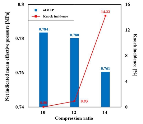
nIMEP and incidence of knock at different compression ratios. Adapted from Lee [48]
In terms of fuel injection timing, Kim et al. [49] demonstrated that retarding the fuel injection timing to create a stratified air–fuel mixture can reduce the occurrence of knock, even in an engine with a high compression ratio. The lean end gas in a stratified mixture created by late fuel injection reduces the combustion temperature of the burned gas near the cylinder wall [54].
As shown in Figure 3, the incidence of knock decreases as the fuel injection timing is retarded in a DI H₂-ICE with a compression ratio of 14. However, the maximum achievable engine output under such knock-suppressed conditions achieved through retarded fuel injection timing at high compression ratios has not been sufficiently investigated. Therefore, further studies are required to evaluate the trade-off between knock mitigation and engine output when optimizing injection timing in DI H2-ICEs with high compression ratios.
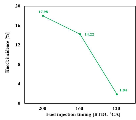
Incidence of knock at different fuel injection timings in a DI H2-ICE with a compression ratio of 14. Adapted from Kim et al. [49].
Furthermore, extensive research has been conducted on water injection to mitigate knock in DI H2-ICEs [48], [54], [55]. Water injected into the cylinder absorbs heat during evaporation, thereby decreasing the charge temperature [48], [56], [57], making it an effective method for reducing engine knock. Because external water injection methods, such as port and manifold water injection in DI H2-ICEs, reduce volumetric efficiency, direct water injection offers greater advantages for increasing engine power output. However, research on direct water injection in DI H₂-ICEs is limited. The studies by Lee [48] and Lee et al. [55] have elucidated the effects of direct water injection on the extension of engine load in DI H₂-ICEs.
For example, Lee [48] reported that compared with injection during the intake stroke, water injection during the compression stroke is more effective at reducing the in-cylinder temperature, suppressing knocking and allowing for greater load extension. Specifically, injecting 8 mg/cycle of water at BTDC 140° CA resulted in an nIMEP of 0.855 MPa with an incidence of knock of 5.11%, whereas injecting the same amount of water at BTDC 260° CA resulted in an nIMEP of 0.840 MPa with a knock incidence exceeding 22%. The authors attributed this phenomenon to the fact that, during the compression stroke, a smaller fraction of the injected water reaches the cylinder wall than during the intake stroke. Even when the same amount of water is injected, injection during the compression stroke leads to greater evaporation before the water impinges on the cylinder wall due to the higher in-cylinder charge temperature. As a result, a more pronounced temperature drop is achieved compared to injection during the intake stroke, resulting in higher nIMEP and lower knock incidence.
Notably, when the same amount of water was injected at BTDC 100° CA, reduced wall wetting resulted in a greater decrease in in-cylinder temperature than at BTDC 140° CA. Consequently, a similar engine load corresponding to an nIMEP of 0.850 MPa was achieved, whereas the incidence of knock further decreased to 0.92%. These experimental results indicate that the degree of wall wetting, determined by the timing of water injection, has a significant influence on the extension of engine load in DI H₂-ICEs. However, systematic investigations into strategies to minimize wall wetting, including the optimization of water injection pressure and timing, remain limited. In addition, further research is required on dedicated direct-water-injection injector designs to enhance spray characteristics and reduce wall impingement.
Because the adoption of charging systems is an effective method for increasing engine power output in conventional ICEs, various studies on charging systems in DI H2-ICEs have also been conducted.
For example, Duan et al. [58] analyzed the combustion characteristics of a turbocharged DI H2-ICE. Like a turbocharged gasoline engine, the turbocharged DI H₂-ICE achieved operation at a BMEP of 1 MPa. However, the maximum pressure rise rate (PRR) of the turbocharged DI H₂-ICE was 0.09 MPa higher than that of the turbocharged gasoline engine. Additionally, the maximum instantaneous HRR and combustion temperature at a BMEP of 1 MPa increased substantially to 83 J/°CA and 1631 K, respectively. respectively. Duan et al. reported that under high-load conditions, these combustion characteristics of the turbocharged DI H₂-ICE increase the combustion temperature, thereby increasing the thermal load on the engine.
Furthermore, Kim et al. [59] reported that a variable geometry type (VGT) turbocharger outperforms a wastegate turbocharger (WGT) in terms of the power output of a DI H₂-ICE because it achieved a higher pressure ratio. As shown in Table 4, compared with the naturally aspirated (NA) condition, the VGT turbocharger increased the maximum engine power output by 165%, whereas the WGT turbocharger resulted in a 117% increase under conditions of 5000 rpm, WOT, and an injection pressure of 3.5 MPa.
Maximum power outputs for the NA, WGT, and VGT turbochargers at 5000 rpm, WOT and injection pressure of 3.5 MPa conditions. Adapted from Kim et al. [59].
Lee [48] applied direct water injection to a supercharged DI H₂-ICE to further increase engine load. As shown in Figure 4, the combined application of intake-pressure boosting and water injection was more effective at increasing the engine load than increased intake pressure alone, regardless of the intake pressure condition. Specifically, at an intake pressure of 0.16 MPa, the simultaneous application of intake-pressure boosting and water injection resulted in an 8% greater maximum GMEP than the application of intake-pressure boosting alone. Notably, when the knock incidence exceeded 5% under all boosted intake-pressure conditions, it was eliminated when water injection was applied simultaneously with intake-pressure boosting because of the charge-cooling effect. Additionally, the simultaneous application of intake-pressure boosting and water injection achieved higher load conditions while maintaining a maximum PRR comparable to that obtained with intake-pressure boosting alone. This result can be attributed to the evaporation of the injected water, which reduces the in-cylinder temperature and consequently moderates the combustion rate. These findings indicate that water injection serves as an effective strategy to mitigate increased engine thermal loads under high-load conditions, as noted by Duan et al. [58], where rapid combustion and elevated temperatures are prevalent.
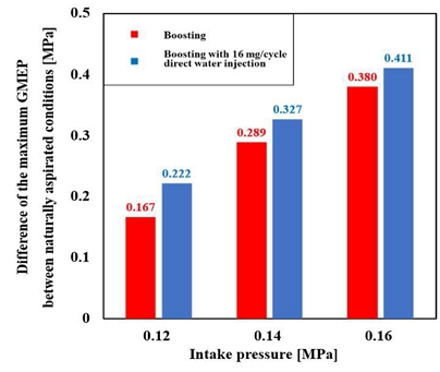
Difference in the maximum GMEP between naturally aspirated conditions for various intake pressures at 1500 rpm, WOT, maximum brake torque (MBT) timing, BTDC 160° CA fuel injection timing, and BTDC 140° CA water injection timing. Adapted from Lee [48]
Kim et al. [60] analyzed the effects of supercharging on engine load and combustion characteristics in a DI H2-ICE with an H2-specific injector. Owing to the increased intake pressure, the maximum GMEP increased by approximately 20% at an intake pressure of 0.12 MPa compared with naturally aspirated conditions, as shown in Table 5. In particular, the rich combustion limit decreased with increasing intake pressure. The authors attributed these phenomena to rapid pressure rise caused by fast combustion during the initial burn duration (IGN–MFB10), as shown in Figure 5. These findings suggest that rapid flame development under boosted conditions limits the increase in engine load, and highlight the need for further research to suppress excessively rapid flame development. In particular, higher-load operation in DI H₂-ICEs may be achievable by combining fuel injection strategies that promote the formation of a locally lean mixture around the spark plug with water injection strategies that reduce combustion rate through charge cooling effects.
Maximum GMEP and rich limit for various intake pressures at 1500 rpm, WOT, MBT timing, and BTDC 80° CA fuel injection timing. Adapted from Kim et al. [60].
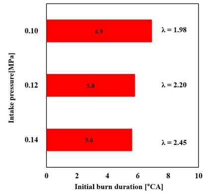
Initial burn duration for various intake pressures at 1500 rpm, WOT, MBT timing, BTDC 80° CA fuel injection timing, and rich limit conditions. Adapted from Kim et al. [60].
In addition to the increase in engine power output, mitigating the high NOₓ emissions resulting from the high adiabatic flame temperature of H2 is a key research challenge in DI H₂-ICEs. This subsection provides an in-depth review of strategies for reducing NOₓ emissions in DI H₂-ICEs.
Because the formation of NOₓ emissions results from high O2 concentrations and combustion temperatures [48], the engine load and air-to-fuel ratio strongly affect NOₓ emissions in H2-ICEs [14]. Therefore, various studies [14], [61]-[65] have investigated lean operation, in which excess air is introduced to create a mixture that is leaner than the stoichiometric condition, thereby reducing the combustion temperature.
According to these previous studies, NOₓ emissions in H2-ICEs decrease sharply when the relative air-to-fuel ratio exceeds λ = 2.0 [9], [48], [58], [66], [67]. As explained by Verhelst et al. [14], the combustion temperature of the H₂–air mixture decreases sharply when the relative air-to-fuel ratio exceeds λ = 2.0. Rahman et al. [46] also demonstrated through a computational model that at various engine speeds, the peak cylinder temperature decreased from 2767 K at φ = 1.2 to below 1650 K at φ = 0.3 and further to 1345 K at φ = 0.2 in a DI H2-ICE.
However, because lean operation can lead to combustion instability in H₂-ICEs, research [68], [69] related to injection strategies in DI H2-ICEs for improving combustion stability under lean conditions has been conducted. For example, Liang et al. [68] reported that employing a split injection strategy reduced the coefficient of variation in maximum pressure (CoVPmax) to 5.90% at λ=3.62, whereas the value for the single-injection case exceeded 8% at the same relative air-to-fuel ratio. Kim [9] also reported that an optimized split injection strategy, in which 70% of the fuel is injected at BTDC 110° CA and the remaining 30% at BTDC 30° CA, can improve combustion stability while maintaining similar NOₓ emission levels. Specifically, a single injection at BTDC 80° CA resulted in a coefficient of variation of gross mean effective pressure (CoVGMEP) of 5.8% with 4 ppm of NOₓ emissions. In contrast, the optimized split injection strategy reduced the CoVGMEP to 1.3% with 5 ppm of NOₓ emissions. The researchers explained that this result was due to the mixture distribution formed by the split injection strategy was more favorable for stable combustion. These experimental findings demonstrate that the combustion instability associated with lean operation can be mitigated through the optimization of fuel injection strategies. However, the absence of studies analyzing in-cylinder mixture distribution using computational fluid dynamics (CFD) simulations suggests that further investigation is required.
Meanwhile, the influence of mixture distribution on combustion characteristics in DI H2-ICEs has stimulated research on fuel injection strategies aimed at reducing NOₓ emissions.
Research has focused first on the effect of fuel injection timing. Verhelst et al. [14] reported that a stratified mixture, resulting from limited mixing time induced by a late injection timing, increases NOₓ emissions under low-load conditions. Specifically, the NOₓ emissions decreased by nearly two orders of magnitude as the fuel injection timing was advanced from BTDC 40° CA to BTDC 140° CA at φ=0.25. The authors suggested that combustion in locally rich regions of a stratified mixture increases the combustion temperature and consequently increases NOₓ emissions.
On the other hand, under high-load conditions, the trend of NOₓ emissions with respect to the fuel injection timing is reversed. For example, at φ=0.7, NOₓ emissions increased with the retardation of the fuel injection timing [70]. Furthermore, Mohammadi et al. [35] reported that the NOₓ emissions at φ = 0.7 with an injection timing of BTDC 300° CA were 8000 ppm, whereas whereas those at BTDC 130° CA and BTDC 100° CA were approximately 6000 ppm and 2000 ppm, respectively, respectively. Verhelst et al. [14] reported that under high-load conditions, an advanced fuel injection timing produces a nearly stoichiometric homogeneous mixture, resulting in high NOₓ emissions, whereas a retarded fuel injection timing produces a stratified mixture that avoids the NOₓ critical relative air-to-fuel ratio (λ ≈ 1.3), thereby reducing overall NOₓ emissions.
While these studies are meaningful in that they provide experimental evidence on the effect of fuel injection timing on NOx emissions in DI H2-ICEs, recent studies employing CFD simulations have elucidated how fuel injection timing influences NOₓ formation.
For example, Qiang et al. [71] reported that the in-cylinder NO concentration field increased with the retardation of the fuel injection timing. Notably, the high concentration mixtures created by late fuel injection in specific regions of the cylinder generated high combustion temperatures, resulting in high NOₓ emissions.
Moreover, studies that focus on other variables, such as fuel injection pressure, injector positions, and angles, have investigated mixture distribution and NOₓ emissions. For example, through CFD simulations, Hu et al. [69] reported that at fixed fuel injection rates and late fuel injection timings, low fuel injection pressures resulted in mixture distributions different from those obtained with high injection pressures. Specifically, owing to the higher jet penetration ability, the fuel injection pressure of 15 MPa resulted in the formation of a rich mixture above φ=0.5 near the cylinder wall, whereas the fuel injection pressure of 2 MPa resulted in the formation of a concentrated mixture above φ=0.5 near the spark plug at a fuel injection timing of BTDC 120° CA. Furthermore, increasing the nozzle diameter of the injector from 2.16 mm to 3.00 mm resulted in a more concentrated mixture near the spark plug, which resulted in accelerated flame propagation. Although this study did not provide specific quantitative data on NOₓ emissions, the CFD-based analysis of mixture distribution and combustion behavior clearly indicates that achieving low NOₓ emissions requires careful optimization of both the fuel injection pressure and the nozzle diameter.
Using CFD simulations, Huang et al. [72] reported that in DI H2-ICEs, the injection pressure controls the mixture homogeneity and stratification patterns, which control NOₓ formation. Notably, mapping NOₓ emissions across the temperature and equivalence ratio space for injection pressures ranging from 15 MPa to 5 MPa (in 5 MPa increments) yielded results consistent with those of Hu et al. [69]. These findings indicate that low injection pressure facilitates the formation of a rich mixture near the spark plug. Furthermore, this mixture distribution by low fuel injection pressure is the primary cause of increased NOₓ emissions. A new finding of this study is that at the same hydrogen injection rate, SOI, and EOI, the mixture distribution obtained with an injection pressure of 3 MPa using a 1.0 mm nozzle diameter was essentially the same as that obtained with an injection pressure of 5 MPa using a 0.8 mm nozzle diameter, resulting in similar combustion characteristics.
Additionally, Chen et al. [73] analyzed the effects of the injector position and injection angle on NOₓ emissions. Specifically, the authors examined NO distributions for three different injector positions and injection angles ranging from 0° to 60° in 15° increments. The results revealed that mixture formation and distribution varied significantly with injector position and injection angle, even under identical operating conditions. Notably, the formation of a rich mixture around the spark plug resulted in high NOₓ emissions, which is consistent with the findings of Hu et al. [69] and Huang et al. [72]. Furthermore, the results of this study indicated that optimizing the injector position and injection angle enables high engine power and low NOₓ emissions by creating an equivalence ratio of approximately 0.6 near the spark plug and a leaner mixture in the peripheral region.
Overall, the findings of these studies indicate that the combustion characteristics and NOₓ emissions in DI H₂-ICEs depend strongly on mixture formation and distribution governed by fuel-injection-related parameters.
Research has also been conducted on water injection as an effective approach for reducing NOₓ emissions. As noted in subsection 4.2.1, water injection not only increases the specific heat capacity of the mixture, thereby suppressing the combustion temperature, but it also absorbs both sensible and latent heat during its evaporation inside the cylinder [48], [56]. These combined effects enable a reduction in in-cylinder temperature, making water injection an effective method for mitigating NOₓ emissions.
Although DI H₂-ICEs employing external water injection limit power output because of reduced volumetric efficiency, this approach has been shown to substantially reduce NOₓ emissions. For example, Nande et al. [74] reported that intake manifold water injection in a DI H2-ICE outperformed the retardation of ignition timing in reducing NOₓ emissions. Specifically, at an IMEP of 0.4 MPa, water injection decreased NOₓ emissions by 27% compared with those obtained with retarded ignition timing, with only 1% loss of thermal efficiency. At an IMEP of 0.8 MPa, injecting 1.4 kg/h of water reduced NOₓ emissions to approximately 900 ppm, whereas retarding the ignition timing by 12° CA produced more than 1000 ppm of NOₓ emissions. The authors attributed this phenomenon to the retardation of the combustion phase caused by water injection, which decreased the peak in-cylinder temperature and thereby reduced NOₓ emissions.
Additionally, Mohamed et al. [75] reported that a significant reduction in NOₓ emissions and high engine performance can be achieved simultaneously in a DI H2-ICE through port water injection without boosting systems. Specifically, injecting 5 kg/h of water into the intake port increased the maximum IMEP from 20 MPa to 24 MPa while reducing NOₓ emissions by approximately 55% compared with those without water injection. The authors presented the retarded combustion phasing with water injection relative to that without water injection, reporting experimental results consistent with those reported by Nande et al. [74]. Furthermore, this study is significant in that it substantially increased the load of DI H₂-ICEs and simultaneously achieved ultralow NOₓ emissions using only a H2-specific injector and port water injection, without any boosting systems.
For DI H₂-ICEs employing direct water injection, Xu et al. [57] reported that both the water injection rate and timing significantly affect NOₓ emissions. Increasing the water injection rate from 1.95 mg/cycle to 4.50 mg/cycle decreased NOₓ emissions from 1333 ppm to 617 ppm at an IMEP of 0.3 MPa. The authors reported that increasing the water injection rate not only increases the specific heat capacity of the mixture but also reduces the O₂ concentration and flame propagation rate of the mixture, thereby reducing NOₓ emissions. Additionally, NOₓ emissions decreased with increasing water injection timing. Specifically, advancing the water injection timing from BTDC 0° CA to BTDC 300° CA decreased the NOₓ emissions from 1590 ppm to 890 ppm at a water injection rate of 2.7 mg/cycle. Notably, injecting water after the ignition timing had a minimal effect on reducing NOₓ emissions. Although the water injection timing coincided with the ignition timing (BTDC 5° CA) and resulted in 1155 ppm of NOₓ emissions, a water injection timing of BTDC 0° CA resulted in 1590 ppm of NOₓ emissions, corresponding to an approximately 37.7% increase. The authors reported that this phenomenon occurs because the fast flame speed of H2 allows the mixture to release most of its heat before the injected water can evaporate, failing to reduce the in-cylinder temperature sufficiently.
In terms of recent DI H₂-ICE research, studies on exhaust gas recirculation (EGR) [76], which effectively reduces NOₓ emissions by diluting the in-cylinder O₂ concentration, as well as post injection strategies [77] for reducing the combustion temperature, have also been actively conducted. Specifically, Lee et al. [77] reported that a post-injection strategy, in which 10% of the total H2 was injected at 160° CA after firing top dead center under 2000 rpm operating conditions, reduced NOₓ emissions by up to 38% without a significant loss in thermal efficiency. The authors further explained this phenomenon based on the Zeldovich reaction mechanism. Furthermore, the authors emphasized that post injection is a cost-effective strategy for reducing NOₓ emissions, because it does not require additional equipment compared with conventional after-treatment systems.
Although various methods have been investigated to reduce NOₓ emissions in DI H2-ICEs, there is a lack of studies directly comparing the effectiveness of these approaches within the same engine configuration or evaluate their combined application. This limitation highlights the need for further research to systematically assess and integrate multiple NOₓ reduction strategies in DI H2-ICEs.
5. Conclusion
This review examined the current state of research on H2-ICEs by integrating insights from fuel properties, combustion characteristics, and recent technological advancements. The findings indicate that H2, while offering clear advantages as a carbon-free fuel, introduces fundamental and interconnected challenges related to power output and NOₓ emissions.
The transition from external mixture formation to DI has emerged as a key technology for overcoming the inherent limitations of H2-ICEs, particularly in terms of volumetric efficiency and abnormal combustion. However, this transition also introduces new constraints, as injector performance and durability have become critical factors limiting engine output. In this context, developments such as H2-specific injectors, optimized injection timing, boosting systems, and water injection have demonstrated considerable potential for improving engine performance.
Despite these advancements, further increases in engine load are increasingly constrained by combustion-related phenomena rather than air supply limitations. In particular, knock occurrence and rapid flame development under boosted conditions have been identified as major factors restricting high-load operation. Although water injection effectively mitigates these issues through charge cooling, systematic investigations into injection strategies, wall wetting, and dedicated injector design remain limited. These observations suggest that future research should focus on integrated control approaches that simultaneously manage fuel injection, water injection, and boosting to regulate combustion behavior.
A similar limitation is observed in NOₓ emission reduction strategies. Lean operation is widely recognized as an effective approach because of its ability to reduce combustion temperature, but its practical application is restricted by combustion instability. Although optimized injection strategies, such as split injection, have shown potential to improve stability under lean conditions, the underlying mechanisms, particularly those related to in-cylinder mixture distribution, remain insufficiently understood. Recent CFD-based studies have provided important insights into the roles of mixture stratification, local equivalence ratio, and temperature distribution in NOₓ formation. However, the lack of systematic integration of experimental and numerical approaches limits the development of generalized design guidelines.
In addition, although various NOₓ reduction techniques, including water injection, EGR, and post-injection, have demonstrated effectiveness, their relative performance and potential synergistic effects have not been systematically evaluated under consistent engine configurations. This limitation indicates the need for comparative and integrated studies to identify optimal strategies for simultaneously improving performance and reducing emissions.
In summary, although substantial progress has been made in advancing DI H2-ICE technologies, the primary challenges have shifted toward system-level optimization. Future research should therefore focus on improving injector performance and durability for gaseous H2 injection, developing integrated combustion control strategies that coordinate fuel injection, water injection, and boosting, applying CFD-based analyses to improve understanding of mixture formation and its effects on combustion and emissions, and establishing unified frameworks that connect experimental and numerical findings. Addressing these challenges will be essential for realizing the full potential of H2-ICEs as a practical and scalable solutions for maritime decarbonization.
Nomenclatures
| BTDC : | Before top dead center |
| CA : | Crank angle |
| CFD : | Computational fluid dynamics |
| CO2 : | Carbon dioxide |
| CoVGMEP : | Coefficient of variation of the gross mean effective pressure |
| CoVPmax : | Coefficient of variation of the maximum pressure |
| DI : | Direct injection |
| EOI : | End of injection |
| FC : | Fuel cell |
| GMEP : | Gross mean effective pressure |
| H2 : | Hydrogen |
| HRR : | Heat release rate |
| ICE : | Internal combustion engine |
| IGN : | Ignition |
| IMEP : | Indicated mean effective pressure |
| MBT : | Maximum brake torque |
| MFB : | Mass fraction burned |
| NOₓ : | Nitrogen oxides |
| nIMEP : | Net indicated mean effective pressure |
| O2 : | Oxygen |
| PFI : | Port fuel injection |
| rpm : | Revolutions per minute |
| SOI : | Start of injection |
| φ : | Fuel‒air equivalence ratio |
| γ : | Specific heat ratio |
| θ : | Crank angle |
| λ : | Relative air–fuel ratio |
Acknowledgments
This research was supported by the 2026 Academic Research Project Fund of the Republic of Korea Navy, Maritime Institute Naval Academy.
Author Contributions
Conceptualization, S. J. Kim and H. M. Lee; Methodology, S. J. Kim, H. M. Beak and H. M. Lee; Software, S. J. Kim; Formal Analysis, S. J. Kim and H. M. Beak; Investigation, S. J. Kim and H. M. Beak; Resources, S. J. Kim; Data Curation S. J. Kim and H. M. Lee; Writing-Original Draft Preparation, S. J. Kim; Writing-Review & Editing, H. M. Lee; Visualization, S. J. Kim; Supervision, H. M. Lee; Project Administration, H. M. Lee; Funding Acquisition, H. M. Lee.
References
- International Energy Agency, Global Energy Review 2025, https://www.iea.org/reports/global-energy-review-2025, , Accessed July 28, 2025.
- International Energy Agency, CO2 Emissions in 2023, https://www.iea.org/reports/co2-emissions-in-2023, , Accessed July 28, 2025.
- International Energy Agency, Aviation and shipping – Analysis, https://www.iea.org/reports/aviation-and-shipping, , Accessed July 28, 2025.
- International Energy Agency, Global CO2 emissions from transport by sub-sector in the Net Zero Scenario, 2000-2030 – Charts – Data & Statistics, https://www.iea.org/data-and-statistics/charts/global-co2-emissions-from-transport-by-sub-sector-in-the-net-zero-scenario-2000-2030-2, , Accessed July 28, 2025.
-
A. A. Ventayol, J. S. L. Lam, X. Bai, and Z. S. Chen, “Comparative life cycle assessment of hydrogen internal combustion engine and fuel cells in shipping,” International Journal of Hydrogen Energy, vol. 109, pp. 774-788, 2025. Available:
[https://doi.org/10.1016/j.ijhydene.2025.02.150]

-
T. Sinigaglia, M. E. S. Martins, and J. C. M. Siluk, “Technological forecasting for fuel cell electric vehicle: A comparison with electric vehicles and internal combustion engine vehicles,” World Patent Information, vol. 71, pp. 102152, 2022. Available:
[https://doi.org/10.1016/j.wpi.2022.102152]
-
X. Liu, K. Reddi, A. Elgowainy, H. Lohse-Busch, M. Wang, and N. Rustagi, “Comparison of well-to-wheels energy use and emissions of a hydrogen fuel cell electric vehicle relative to a conventional gasoline-powered internal combustion engine vehicle,” International Journal of Hydrogen Energy, vol. 45, no. 1, pp. 972-983, 2020. Available:
[https://doi.org/10.1016/j.ijhydene.2019.10.192]
-
D. Elrhoul, M. Romero Gómez, and M. Naveiro, “Review of green hydrogen technologies application in maritime transport,” International Journal of Green Energy, vol. 20, no. 15, pp. 1800-1825, 2023. Available:
[https://doi.org/10.1080/15435075.2023.2194384]
- S. Kim, Optimization of a Split Injection Strategy in a Hydrogen Direct-Injection Spark Ignition Engine, Master’s Thesis, Department of Mechanical Engineering, Seoul National University, Republic of Korea, 2025.
- I. S. Seddiek, M. M. Elgohary, and N. R. Ammar, “The hydrogen-fuelled internal combustion engines for marine applications with a case study,” Brodogradnja: An International Journal of Naval Architecture and Ocean Engineering for Research and Development, vol. 66, no. 1, pp. 23-38, 2015.
-
R. Krakowski, “Analysis of Replacement of Internal Combustion Engine with the Hydrogen Fuel Cell in Ship Powertrain,” Advances in Science and Technology Research Journal, vol. 18, no. 5, 2024.
[https://doi.org/10.12913/22998624/190130]
- M. M. El-Gohary, “Design of marine hydrogen internal combustion engine,” Alexandria Engineering Journal, vol. 47, no. 1, pp. 57-65, 2008.
-
C. M. White, R. R. Steeper, and A. E. Lutz, “The hydrogen-fueled internal combustion engine: a technical review,” International Journal of Hydrogen Energy, vol. 31, no. 10, pp. 1292-1305, 2006. Available:
[https://doi.org/10.1016/j.ijhydene.2005.12.001]
-
S. Verhelst and T. Wallner, “Hydrogen-fueled internal combustion engines,” Progress in Energy and Combustion Science, vol. 35, no. 6, pp. 490-527, 2009. Available:
[https://doi.org/10.1016/j.pecs.2009.08.001]
-
L. M. Das, “Hydrogen engines: a view of the past and a look into the future,” International Journal of Hydrogen Energy, vol. 15, no. 6, pp. 425-443, 1990. Available:
[https://doi.org/10.1016/0360-3199(90)90200-I]
-
L. M. Das, “Fuel induction techniques for a hydrogen operated engine,” International Journal of Hydrogen Energy, vol. 15, no. 11, pp. 833-842, 1990. Available:
[https://doi.org/10.1016/0360-3199(90)90020-Y]
-
I. J. S. Veldhuis, R. N. Richardson, and H. B. J. Stone, “Hydrogen fuel in a marine environment,” International Journal of Hydrogen Energy, vol. 32, no. 13, pp. 2553-2566, 2007. Available:
[https://doi.org/10.1016/j.ijhydene.2006.11.013]
-
Z. Stępień, “A comprehensive overview of hydrogen-fueled internal combustion engines: Achievements and future challenges,” Energies, vol. 14, no. 20, pp. 6504, 2021. Available:
[https://doi.org/10.3390/en14206504]
-
S. Furuhama, K. Yamane, and I. Yamaguchi, “Combustion improvement in a hydrogen fueled engine,” International Journal of Hydrogen Energy, vol. 2, no. 3, pp. 329-340, 1977. Available:
[https://doi.org/10.1016/0360-3199(77)90027-1]
-
J. Duan, F. Liu, and B. Sun, “Backfire control and power enhancement of a hydrogen internal combustion engine,” International Journal of Hydrogen Energy, vol. 39, no. 9, pp. 4581-4589, 2014. Available:
[https://doi.org/10.1016/j.ijhydene.2013.12.175]
-
V. Kumar, D. Gupta, and N. Kumar, “Hydrogen use in internal combustion engine: A review,” International Journal of Advanced Culture Technology, vol. 3, no. 2, pp. 87-99, 2015.
[https://doi.org/10.17703/IJACT.2015.3.2.87]
-
H. Li and G. A. Karim, “Knock in spark ignition hydrogen engines,” International Journal of Hydrogen Energy, vol. 29, no. 8, pp. 859-865, 2004. Available:
[https://doi.org/10.1016/j.ijhydene.2003.09.013]
- R. D. Gandhi, “Use of hydrogen in internal combustion engine”, International Journal of Engineering and Technical Research, vol. 3, no. 2, pp. 207-216, 2015.
-
T. Iijima and T. Takeno, “Effects of temperature and pressure on burning velocity,” Combustion and Flame, vol. 65, no. 1, pp. 35-43, 1986. Available:
[https://doi.org/10.1016/0010-2180(86)90070-2]
-
D. D. S. Liu and R. MacFarlane, “Laminar burning velocities of hydrogen-air and hydrogen-air steam flames,” Combustion and Flame, vol. 49, no. 1-3, pp. 59-71, 1983. Available:
[https://doi.org/10.1016/0010-2180(83)90151-7]
-
S. Verhelst, R. Woolley, M. Lawes, and R. Sierens, “Laminar and unstable burning velocities and Markstein lengths of hydrogen–air mixtures at engine-like conditions,” Proceedings of the Combustion Institute, vol. 30, no. 1, pp. 209-216, 2005. Available:
[https://doi.org/10.1016/j.proci.2004.07.042]
- E. Berger, C. Bock, M. Fisher, M. Gruber, G. Kiesgen, and H. Rottengruber, “The new BMW12-cylinder hydrogen engine clean efficient and powerful vehicle powertrain,” FISITA 2006 World Automotive Congress, 2006.
- K. Binder and G. Withalm, “Mixture formation and combustion in interaction with the hydrogen storage technology,” Hydrogen Energy Progress, vol. 3, pp. 1103, 1980.
-
S. Verhelst, P. Maesschalck, N. Rombaut, and R. Sierens, “Increasing the power output of hydrogen internal combustion engines by means of supercharging and exhaust gas recirculation,” International Journal of Hydrogen Energy, vol. 34, no. 10, pp. 4406-4412, 2009. Available:
[https://doi.org/10.1016/j.ijhydene.2009.03.037]
-
J. Francfort and D. Karner, “Hydrogen ICE vehicle testing activities,” SAE Technical Paper No. 2006-01-0433, 2006. Available:
[https://doi.org/10.4271/2006-01-0433]
-
G. D’Errico, A. Onorati, and S. Ellgas, “1D thermo-fluid dynamic modelling of an SI single-cylinder H2 engine with cryogenic port injection,” International Journal of Hydrogen Energy, vol. 33, no. 20, pp. 5829-5841, 2008. Available:
[https://doi.org/10.1016/j.ijhydene.2008.05.096]
- M. Hallmannsegger, Potentials of the four-stroke Otto engine with PFI of cryogenic hydrogen, Ph. D. Dissertation, Graz University of Technology, 2005.
- C. B. Srinivasan and R. Subramanian, “Hydrogen as a spark ignition engine fuel technical review,” International Journal of Mechanical and Mechatronics Engineering, vol. 14, pp. 111-117, 2014.
-
M. Faizal, L. S. Chuah, C. Lee, A. Hameed, J. Lee, and M. Shanker, “Review of hydrogen fuel for internal combustion engines”, Journal of Mechanical Engineering Research and Developments, vol. 42, no. 3, pp. 36-46, 2019.
[https://doi.org/10.26480/jmerd.03.2019.35.46]
-
A. Mohammadi, M. Shioji, Y. Nakai, W. Ishikura, and E. Tabo, “Performance and combustion characteristics of a direct injection SI hydrogen engine,” International Journal of Hydrogen Energy, vol. 32, no. 2, pp. 296-304, 2007. Available:
[https://doi.org/10.1016/j.ijhydene.2006.06.005]
-
S. Furuhama, K. Yamane, and I. Yamaguchi, “Combustion improvement in a hydrogen fueled engine,” International Journal of Hydrogen Energy, vol. 2, no. 3, pp. 329-340, 1977. Available:
[https://doi.org/10.1016/0360-3199(77)90027-1]
- D. Bansal, C. Tang, M. Schneider, P. Grabner, G. Lurf, N. Kunder, and M. Wieser, “Understanding lubricant induced pre-ignition in hydrogen internal combustion engines,” Proceedings of the International Vienna Motor Symposium 2025.
- W. F. Stockhausen, R. J. Natkin, and L. Reams, “Crankcase ventilation system for a hydrogen fueled engine”, U.S. Patent No. 6,606,982, Aug 19, 2003.
-
M. Yeganeh, K. Rönn, S. Karimkashi, Q. Cheng, P. Hlaing, J. Hyvönen, V. Vuorinen, O. Kaario, and M. Larmi, “On the hydrogen pre-ignition phenomenon induced by engine lubricating oils with different calcium contents in a rapid compression expansion machine,” Applications in Energy and Combustion Science, vol. 23, pp. 100339, 2025. Available:
[https://doi.org/10.1016/j.jaecs.2025.100339]
-
E. Distaso, G. Calo, R. Amirante, P. De Palma, M. Mehl, M. Pelucchi, A. Stagni, and P. Tamburrano, “Linking lubricant oil contamination to pre-ignition events in hydrogen engines–The HyLube mechanism,” Fuel, vol. 379, pp. 133041, 2025. Available:
[https://doi.org/10.1016/j.fuel.2024.133041]
-
L. M. Das, “Near-term introduction of hydrogen engines for automotive and agricultural application,” International Journal of Hydrogen Energy, vol. 27, no. 5, pp. 479-487, 2002. Available:
[https://doi.org/10.1016/S0360-3199(01)00163-X]
-
M. R. Swain, G. J. Schade, and M. N. Swain, “Design and testing of a dedicated hydrogen-fueled engine,” SAE Technical Paper No. 961077, 1996, Available:
[https://doi.org/10.4271/961077]
-
S. J. Lee, H. S. Yi, and E. S. Kim, “Combustion characteristics of intake port injection type hydrogen fueled engine,” International Journal of Hydrogen Energy, vol. 20, no. 4, pp. 317-322, 1995. Available:
[https://doi.org/10.1016/0360-3199(94)00052-2]
-
H. S. Yi, K. Min, and E. S. Kim, “The optimised mixture formation for hydrogen fuelled engines,” International Journal of Hydrogen Energy, vol. 25, no. 7, pp. 685-690, 2000. Available:
[https://doi.org/10.1016/S0360-3199(99)00082-8]
-
N. Saravanan and G. Nagarajan, “An experimental investigation on optimized manifold injection in a direct-injection diesel engine with various hydrogen flowrates,” Proceedings of the Institution of Mechanical Engineers, Part D: Journal of Automobile Engineering, vol. 221, no. 12, pp. 1575-1584, 2007. Available:
[https://doi.org/10.1243/09544070JAUTO609]
-
M. M. Rahman, M. Kamil, and R. A. Bakar, “Engine performance and optimum injection timing for 4-cylinder direct injection hydrogen fueled engine,” Simulation Modelling Practice and Theory, vol. 19, no. 2, pp. 734-751, 2011. Available:
[https://doi.org/10.1016/j.simpat.2010.10.006]
-
C. Park, Y. Kim, S. Oh, J. Oh, Y. Choi, H. Baek, S. W. Lee, and K. Lee, “Effect of fuel injection timing and injection pressure on performance in a hydrogen direct injection engine,” International Journal of Hydrogen Energy, vol. 47, no. 50, pp. 21552-21564, 2022. Available:
[https://doi.org/10.1016/j.ijhydene.2022.04.274]
- S. Lee, Optimization of Combustion Chamber and Load Expansion in a Hydrogen Direct Injected Spark Ignition Engine, Ph. D. Dissertation, Department of Mechanical Engineering, Seoul National University, Republic of Korea, 2024.
-
S. Kim, J. Lee, S. Lee, S. Lee, K. Kim, and K. Min, “Effects of various compression ratios on a direct injection spark ignition hydrogen-fueled engine in a single-cylinder engine,” International Journal of Automotive Technology, vol. 25, no. 5, pp. 1159-1172, 2024. Available:
[https://doi.org/10.1007/s12239-024-00096-6]
-
Y. Li, W. Gao, P. Zhang, Z. Fu, and X. Cao, “Influence of the equivalence ratio on the knock and performance of a hydrogen direct injection internal combustion engine under different compression ratios,” International Journal of Hydrogen Energy, vol. 46, no. 21, pp. 11982-11993, 2021. Available:
[https://doi.org/10.1016/j.ijhydene.2021.01.031]
-
Y. Li, W. Gao, Y. Li, Z. Fu, and J. Zou, “Numerical investigation on combustion and knock formation mechanism of hydrogen direct injection engine,” Fuel, vol. 316, pp. 123302, 2022. Available:
[https://doi.org/10.1016/j.fuel.2022.123302]
-
Y. Ye, W. Gao, Y. Li, P. Zhang, and X. Cao, “Numerical study of the effect of injection timing on the knock combustion in a direct-injection hydrogen engine,” International Journal of Hydrogen Energy, vol. 45, no. 51, pp. 27904-27919, 2020. Available:
[https://doi.org/10.1016/j.ijhydene.2020.07.117]
-
T. Shudo, W. K. Cheng, T. Kuninaga, and T. Hasegawa, “Reduction of cooling loss in hydrogen combustion by direct injection stratified charge,” SAE transactions, pp. 2118-2123, 2003.
[https://doi.org/10.4271/2003-01-3094]
-
J. Mortimer, F. Poursadegh, M. Brear, S. Yoannidis, J. Lacey, and Y. Yang, “Extending the knock limits of hydrogen DI ICE using water injection,” Fuel, vol. 335, pp. 126652, 2023. Available:
[https://doi.org/10.1016/j.fuel.2022.126652]
-
S. Lee, J. Lee, S. Kim, K. Kim, S. Lee, K. Min, “Experimental research of water direct injection in the cylinder for the nitrogen oxides reduction and high load extension of the hydrogen direct injection spark ignition engine,” International Journal of Engine Research, pp. 14680874251325311, 2025. Available:
[https://doi.org/10.1177/14680874251325311]
-
V. Subramanian, J. M. Mallikarjuna, and A. Ramesh, “Effect of water injection and spark timing on the nitric oxide emission and combustion parameters of a hydrogen fuelled spark ignition engine,” International Journal of Hydrogen Energy, vol. 32, no. 9, pp. 1159-1173, 2007. Available:
[https://doi.org/10.1016/j.ijhydene.2006.07.022]
-
P. Xu, C. Ji, S. Wang, X. Cong, Z. Ma, C. Tang, H. Meng, and C. Shi, “Effects of direct water injection on engine performance in a hydrogen (H2)-fueled engine at varied amounts of injected water and water injection timing,” International Journal of Hydrogen Energy, vol. 45, no. 24, pp. 13523-13534, 2020. Available:
[https://doi.org/10.1016/j.ijhydene.2020.03.011]
-
Y. Duan, B. Sun, Q. Li, X. Wu, T. Hu, and Q. Luo, “Combustion characteristics of a turbocharged direct-injection hydrogen engine,” Energy Conversion and Management, vol. 291, pp. 117267, 2023. Available:
[https://doi.org/10.1016/j.enconman.2023.117267]
-
C. Kim, C. Park, Y. Kim, and Y. Choi, “Power characteristics with different types of turbochargers for lean boosted hydrogen direct injection engine in NOₓ-free operation,” Heliyon, vol. 9, no. 3, 2023.
[https://doi.org/10.1016/j.heliyon.2023.e14186]
-
S. Kim, H. Lee, and K. Min, “Effects of supercharging on combustion and NOₓ emission characteristics under various relative air-to-fuel ratios in a hydrogen DISI engine,” Journal of Advanced Marine Engineering and Technology, vol. 49, no. 3, pp. 107-115, 2025. Available:
[https://doi.org/10.5916/jamet.2025.49.3.107]
- S. Verstraeten, R. Sierens, and S. Verhelst, “A high speed single cylinder hydrogen fuelled internal combustion engine,” FISITA 2004 World Automotive Congress, 2004. Available: http://hdl.handle.net/1854/LU-303114, .
- R. Sierens, S. Verhelst, and S. Verstraeten, “EGR and lean combustion strategies for a single cylinder hydrogen fuelled IC engine”, Beograd 2005 EAEC European Automotive Congress. JUMV-Yugoslav Society of Automotive Engineers, 2005.
- S. Verhelst, S. Verstraeten, and R. Sierens, “A comparison between lean burn operation and stoichiometric operation with EGR for a hydrogen fuelled IC engine”, 16th World hydrogen energy conference (WHEC), Lyon, France. pp. 13-16. 2006.
-
R. W. Schefer, C. White, and J. Keller, “Lean Hydrogen Combustion,” Lean Combustion, Derek Dunn-rankin, Academic Press, 2008. Available:
[https://doi.org/10.1016/B978-012370619-5.50009-1]
-
T. Shudo, K. Omori, and O. Hiyama, “NOₓ reduction and NO2 emission characteristics in rich-lean combustion of hydrogen,” International Journal of Hydrogen Energy, vol. 33, no. 17, pp. 4689-4693, 2008. Available:
[https://doi.org/10.1016/j.ijhydene.2008.05.034]
-
Y. Luo, B. Wu, Q. Li, X. Tang, Z. Yang, C. Wu, and T. Wu, “Experimental and simulation research on the lean combustion characteristics of direct-injection hydrogen engine,” International Journal of Hydrogen Energy, vol. 68, pp. 398-409, 2024. Available:
[https://doi.org/10.1016/j.ijhydene.2024.04.184]
-
Y. Takagi, H. Mori, Y. Mihara, N. Kawahara, and E. Tomita, “Improvement of thermal efficiency and reduction of NOₓ emissions by burning a controlled jet plume in high-pressure direct-injection hydrogen engines,” International Journal of Hydrogen Energy, vol. 42, no. 41, pp. 26114-26122, 2017. Available:
[https://doi.org/10.1016/j.ijhydene.2017.08.015]
-
Z. Liang, F. Xie, K. Lai, H. Chen, J. Du, and X. Li, “Study of single and split injection strategies on combustion and emissions of hydrogen DISI engine,” International Journal of Hydrogen Energy, vol. 49, pp. 1087-1099, 2024. Available:
[https://doi.org/10.1016/j.ijhydene.2023.10.060]
-
Z. Hu, S. Yuan, H. Wei, Z. Huang, S.H. Wei, and L. Zhou, “High-pressure injection or low-pressure injection for a direct injection hydrogen engine?,” International Journal of Hydrogen Energy, vol. 59, pp. 383-389, 2024. Available:
[https://doi.org/10.1016/j.ijhydene.2024.02.018]
-
T. Wallner, S. Ciatti, and B. Bihari, Investigation of injection parameters in a hydrogen DI engine using an endoscopic access to the combustion chamber, SAE Technical Paper No. 2007-01-1464, 2007. Available:
[https://doi.org/10.4271/2007-01-1464]
-
Y. Qiang, X. Cai, S. Xu, F. Wang, L. Zhang, S. Wang, and C. Ji, “Effect of injection strategy on the hydrogen mixture distribution and combustion of the hydrogen-fueled engine with passive pre-chamber ignition under lean burn condition,” Fuel, vol. 375, pp. 132610, 2024. Available:
[https://doi.org/10.1016/j.fuel.2024.132610]
-
Z. Huang, S. Yuan, H. Wei, L. Zhong, Z. Hu, Z. Liu, C. Liu, H. Wei, and L. Zhou, “Effects of hydrogen injection timing and injection pressure on mixture formation and combustion characteristics of a hydrogen direct injection engine,” Fuel, vol. 363, pp. 130966, 2024. Available:
[https://doi.org/10.1016/j.fuel.2024.130966]
-
W. Chen, C. Lu, Q. Zuo, C. Kou, R. Shi, H Wang, D Ning, Z Shen, and G. Zhu, “Combustion characteristics analysis and performance evaluation of a hydrogen engine under direct injection plus lean burn mode,” Journal of Cleaner Production, vol. 470, pp. 143323, 2024. Available:
[https://doi.org/10.1016/j.jclepro.2024.143323]
-
A. M. Nande, T. Wallner, and J. Naber, Influence of water injection on performance and emissions of a direct-injection hydrogen research engine, SAE Technical Paper No. 2008-01-2377, 2008. Available:
[https://doi.org/10.4271/2008-01-2377]
-
M. Mohamed, A. Biswal, X. Wang, H. Zhao, A. Harington, J. Hall, and M. Peckham, “Exploring the benefits of hydrogen-water injection technology in internal combustion engines: A rigorous experimental study,” International Journal of Engine Research, vol. 26, no. 5, pp. 724-740, 2025. Available:
[https://doi.org/10.1177/14680874241288624]
-
Y. Kim, J. Ha, C. Park, Y. Choi, K. Lee, H. Baek, S. Lee, and J. Lee, “Effects of exhaust gas recirculation on nitrogen oxides, brake torque and efficiency in a hydrogen direct injection spark ignition engine,” International Journal of Engine Research, vol. 25, no. 6, pp. 1124-1135, 2024. Available:
[https://doi.org/10.1177/14680874231220767]
-
S. Lee, K. Kim, J. Lee, Y. Kim, J. Cho, S. Oh, and K. Min “NOₓ reduction in hydrogen-fueled direct-injected spark ignition (DISI) engine using post-injection strategy: Experimental and chemical kinetics approaches,” Energy, vol. 324, pp. 136085, 2025. Available:
[https://doi.org/10.1016/j.energy.2025.136085]