Case study on operating characteristics of gas fueled ship under the conditions of load variation
Copyright © The Korean Society of Marine Engineering
This is an Open Access article distributed under the terms of the Creative Commons Attribution Non-Commercial License (http://creativecommons.org/licenses/by-nc/3.0), which permits unrestricted non-commercial use, distribution, and reproduction in any medium, provided the original work is properly cited.
Abstract
The use of gas as fuel, particularly liquefied natural gas (LNG), has increased in recent years owing to its lower sulfur and particulate emissions compared to fuel oil or marine diesel oil. LNG is a low temperature, volatile fuel with very low flash point. The major challenges of using LNG are related to fuel bunkering, storing, and handling during ship operation. The main components of an LNG fuel system are the bunkering equipment, fuel tanks, vaporizers/heaters, pressure build-up units (PBUs), and gas controlling units. Low-pressure dual-fuel (DF) engines are predominant in small LNG-powered vessels and have been operating in many small- and medium-sized ferries or LNG-fueled generators.(Tamura, K., 2010; Esoy, V., 2011[1][2]) Small ships sailing at coast or offshore rarely have continuous operation at constant engine load in contrast to large ships sailing in the ocean. This is because ship operators need to change the engine load frequently due to various obstacles and narrow channels.
Therefore, controlling the overall system performance of a gas supply system during transient operations and decision of bunkering time under a very poor infrastructure condition is crucial. In this study, we analyzed the fuel consumption, the system stability, and the dynamic characteristics in supplying fuel gas for operating conditions with frequent engine load changes using a commercial analysis program. For the model ship, we selected the ‘Econuri’, Asia’s first LNG-powered vessel, which is now in operation at Incheon Port of South Korea.
Keywords:
LNG, Gas fueled ship, Fuel supply system, Low-pressure Dual-fuel engine, LNG bunkering1. Introduction
Lately, to reduce air pollution arising due to vessels, the International Maritime Organization (IMO) and related agencies have strengthened regulations for emissions such as NOx, SOx, CO2, and particulates. These emissions can cause increased atmospheric temperature, air pollution, and many harmful problems for living things on earth. To reduce air pollution from vessels, the IMO and related agencies have strengthened emission regulations. As a clean source of energy, the use of LNG as marine fuel has increased in recent years due to stricter regulations regarding diesel emission, the relative abundance of natural gas, and long-term economics.(Econnomides, et al., 2006; El-Gohary and Morsy, M., 2012[3][4]) Its use will contribute to reduction of emissions as it contains negligible or no sulfur. In addition, the new mandatory code for ships fueled by gases or other low-flash point fuels (IGF Code, 2015[5]) was adopted by IMO’s Maritime Safety Committee (MSC) during its 95th session at its London headquarters from June 3–12, 2015. The MSC adopted the code, along with amendments, to make it mandatory under the International Convention for the Safety of Life at Sea (SOLAS).
However, uncertain future projections of LNG price and availability may not convince the ship owners to adopt the use of gaseous bunker fuel. The design of a more complicated system and the fact that LNG technology is relatively new may cause delays in the installation and construction.(Kim et al., 2015; Oka et al. 2013[6][7]) The uncertainties, related to the use LNG as bunker fuel are presented in Table 1.
The small size of most public service vessels, the limited amount of space, and the frequent variation of engine load like that of ‘Econuri’, make it difficult to operate with an acceptable level of environmental performance or management. In addition, ships sailing offshore or in coastal waters rarely have continuous voyages at constant engine power compared to oceangoing ships. Therefore, in terms of LNG bunkering, ship operators have difficulty in knowing the important factors to consider, such as the fuel consumption during frequent load changes, exact level of LNG fuel storage tank, and estimation of possible operating time. The LNG for these vessels will be supplied from a tanker truck at a special station.
This study assessed the dynamic characteristics of the fuel gas supply system as well as the gas consumption during variable load operation, and the fuel remaining in the fuel tank for the next LNG bunkering. ‘Econuri’, which installed IMO type C tank (IMO, 1993) and consisted of fuel gas supply system (FGSS) of low-pressure type (approximately 5 barg) with four-stroke DF engines, was selected.
2. Analysis of operating characteristics in fuel gas supply system
2.1 Flow and pressure drop in horizontal gas pipes
In the LNG fuel supply system for DF engines, both liquid and gas fuel flow through the piping system. The fluid is transported by supply pipes to the various components of the system. From the fuel storage tanks, the liquid fuel flows to the vaporizers where it exchanges heat and changes from liquid to gas. The gas is further heated and flows to the engine system (Cho et al. 2013[8]).
LNG is treated as an incompressible fluid because its compressibility factor is considerably low. An incompressible fluid has a constant density, i.e., the fluid density is neither affected by pressure nor temperature changes. In contrast, the density of a compressible fluid is not constant. Since the gasified LNG in a vaporizer is compressible, its density is influenced by both pressure and temperature changes. It should be noted that for compressible fluids, the thermal energy is converted into mechanical energy with the gas flow (Rennels et al. 2012[9]). This factor makes the calculation of pressure drop for compressible fluids significantly more difficult compared to that of incompressible fluids. Rennels et al. 2012[9] suggested some methods to take into account the pressure drop in compressible fluids. Table 2 shows the classified methods either by applying Bernoulli’s equation for incompressible flow in Equation (1) to approximate compressible flow or by using ideal gas equations for compressible flow. In these considerations, it is assumed that the pipe is horizontal with constant diameter throughout the process of simulation.

The methods of adjusting Bernoulli’s equation for incompressible flow to approximate compressible flow according to Rennels et al. (2012)[9]
| (1) |
| (2) |
Here, p, V, ρ, g, z, and hL are the pressure [Pa], fluid velocity [m/s], gravity [m/s2], vertical elevation [m], and head loss [m], respectively. The method using the inlet and outlet properties of the flow is the simplest method to determine the pressure loss for compressible flow.(Kim, 2015[10]). It is suitable for piping systems with less than 10% pressure loss. Subsequently, Bernoulli’s equation, Equation (1), for incompressible flow can be transformed to Equation (3).
| (3) |
2.2 Selection of model ship and LNG fuel
The ‘Econuri’ vessel of Incheon Port Authority was selected as model ship to assess the dynamic characteristics of the fuel gas system during operation. It is the first LNG-fueled vessel in Asia and has adopted a dual fuel diesel engine (DFDE) system as presented in Table 3. The vessel has 20 m3 (IMO type-C) LNG storage tank, vaporizer, generators (Wartsila 9L20DF) rated at 1584kW at maximum continuous rating (MCR), GVU, and motors (STADT, 700kW, 2sets) for electric propulsion. It was known that the sailing distance of the ship is 895km under nominal continuous rating (NCR) operation. Table 4 shows the fuel consumption depending on the generator load to operate the propulsion motors.
Calorific conditions were applied using 54.86 MJ/kg, according to the LNG conversion table from Korea Gas Corporation (KOGAS) website (www.KOGAS.or.kr[11]]). The gas consumption was also calculated with reference to Wartsila’s 20 DF engine. At maximum load, the gas consumption was calculated to be 245.4 kg/h as shown in Table 3. The total amount of LNG used in the ship was supplied by KOGAS. The composition of this gas coming from Qatar is methane 89.18%, ethane 7.07, propane 2.5%, n-butane 0.69, i-butane 0.46, nitrogen 0.09 and etc.
2.3 Initial condition for system process
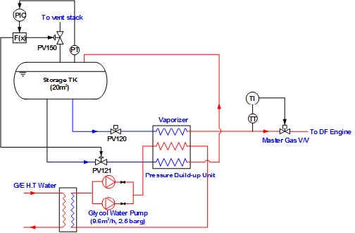
Figure 1 shows the general low-pressure fuel gas supply system from the inlet stream of LNG to the master gas valve. These are based on the engine specification of a Wartsila DF engine of the type 9L20DF with a total output power of 1584 kW. The mass flow of LNG fuel was set to the estimated maximum fuel consumption of 245.4 kg/h. The initial operating pressure was set to 6.5 barg because the master gas valve requires a minimum inlet pressure of 5 barg at normal conditions. In addition, a 20°C inlet temperature to the master valve was set in the simulation.
The models in Aspen HYSYS (2015)[12] used the fluid package Peng Robinson for the dynamic simulations, which is an equation of state often used for natural gas system.(Lee et al. 2014; Ekwonu et al. 2013; Yuan et al. 2015[13]-[15]) The LNG tank was kept at −162°C and a pressure of 6 bar in the tank. The tank volume was set to 20 m3 and to an LNG liquid level of 95%, which is a common practice at bunkering.
The actual start-up procedure must go through a cooling down process as well as an auxiliary equipment like glycol water pump. However, in the numerical analysis, the process of cooling down was not taken into account. During normal operating load, natural gas for fuel should be supplied to the DF engine under the design conditions of 300 kg/h and 5 barg. Main conditions for setting initial start-up, normal load, load down, and load up are as follows:
(a) Conditions for initial start-up and normal load
- The initial tank level is to be set to 95% and the tank pressure is to be 6.5 barg.
- The master gas valve is to be opened.
(b) Conditions for load down
- To change the operating condition, the engine must be in stable state during load up.
- Flow controller (FIC) changes the flow rate by the load in accordance with Table 4.
(c) Conditions for load up
- To change the operating condition, the engine must be in stable state during load down.
- Flow controller (FIC) changes the flow rate by the load in accordance with Table 4.
3. Result and Discussion
3.1 The estimation of ship speed by loads
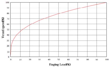
The flow rate can be determined after confirming the service speed of the ship by loads. In this case, the service speed was calculated by the propeller law as presented in Figure 2 and Table 5, since we did not have the voyage data of the model ship.(ABS, 2015[16]) The propulsion system of the Econuri vessel has two 700 kW propulsion motors, so we assumed that it can sail a maximum speed of 15 knots.
According to the propeller law, the ship pilot has no problem at the time of arrival and departure because it can sail at a speed of 11.91 knots with a 50% engine load.
3.2 Case study 1: Navigation in Incheon harbor of ‘Econuri’ vessel
‘Econuri’ vessel was built to guide Incheon harbor; therefore, we estimated the fuel consumption for various loads using the voyaging information from the harbor. One sailing time takes about 40 min and from this, it was assumed that the departing, arriving, and voyaging times were 5, 5, and 30 min, respectively. We determined the loads at the time of arrival/ departure at 50% of the power output, and in case of the 30-min voyage, predicted the NCR operation of 75% which was the expected pattern of sailing.
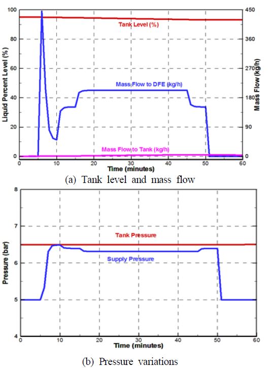
Figure 3 (a) and (b) show the characteristic curves of tank level, gas consumption to DF engine, and return to fuel tank by PBU in case of the 40 min voyage of Econuri. After 5 min, flow rate was suddenly increased by opening the GVU, but there was no significant change in pressure. In 10 min, the generator operation was started, and the flow rate of 180 kg/h was supplied continuously without fluctuation. After 15 min of the voyage, the engine load reached 75% of the economic speed, then NCR condition was maintained for 30 min. The return flowrate supplied into the top of the LNG fuel tank was increased in accordance with increasing load and kept stable at the pressure of fuel gas. The fuel gas consumed was about 0.58 m3 for 40 min of operation. Thus, if the ship has a bunkering of up to 95% of the fuel tank volume and performs re-bunkering at 30% volume, it is possible to sail approximately 22 times at Incheon port.
It was verified that there was no problem in performing the navigation for port guidance considering the change of pressure, temperature, and other factors in the system without concern for bunkering.
3.3 Case study 2: Voyage outside the port under the conditions of sudden load variation
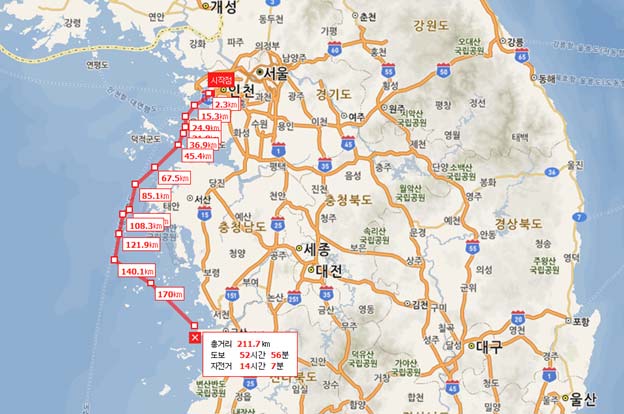
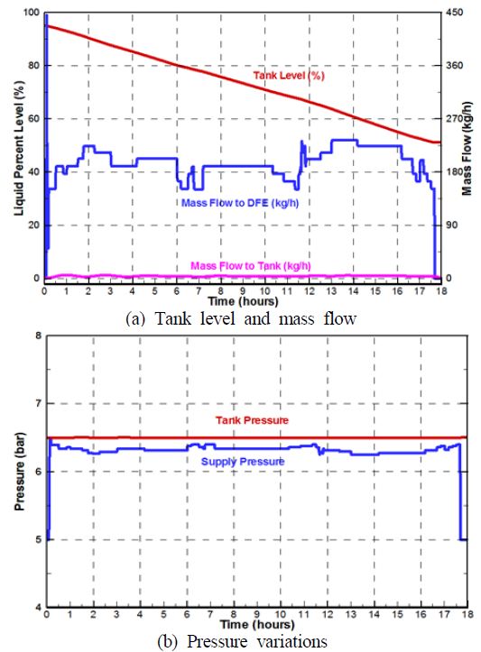
For this case, the ship navigates from Incheon Port to the Gunsan coastal waters, Jeollabuk-do, through narrow channels for 2 h as shown in Figure 4. Assuming that the engine load is 50% during entering/departing, and performs abrupt veering and steering when navigating, we examined the availability of the model ship for a stable navigation under the severe conditions such as when the load is decreased from 90 to 70% rapidly or increased from 50 to 70%. In actual navigation, since the load changes due to frequent radical steering, veering, and avoiding, system stability is a very important factor.
Figure 5 (a) and (b) show the characteristic curves of fuel gas supplying the engines. There was a sudden fluctuation in the flow when the GVU was opened, but the pressure did not have significant changes. After that, to get out of the narrow channel for 2 h, abrupt speed up and slow down were performed at approximately 50–70% of engine load. At this time, the gas pressure met the required supply pressure of 6.0–6.5 barg without any fluctuations.
Furthermore, despite the rapid power variation decrease from 90 to 70% of the load, it was confirmed that the gas pressure and flow rate for DF engines maintained a stable response with no significant variation. Moreover, as can be seen from the figures, it was shown that Econuri has a sailing capability out of the harbor without difficulty or bunkering to voyage the Gunsan coastal, Jeollabuk-do and return to Incheon Port. At this time, the average ship speed was 11.9 knots and it can sail for 17 h and 30 min. Fuel consumption was 8.6 m3.
From the above stated results, even if a sudden change in the loads or an emergency occurs, the ship can still maintain a stable system.
4. Conclusion
This study analyzed the dynamic characteristics of an LNG fuel gas supply system as well as the gas consumption during variable load operations, and the remaining fuel tank volume for the next LNG bunkering. The first LNG-fueled vessel in Asia, Econuri, of Incheon Port Authority in Korea, was selected.
As a result of analyzing the operating characteristics of a gas-fueled ship, the major findings are given below:
(a) Through examination of navigation patterns of Econuri, we verified that stable operation was available even at shutdown and radical load change in gas supply system like drastic changes of flow rate or fuel pressure.
(b) Approximately 2.9 % of LNG fuel was consumed in the navigation with port guidance of Econuri. During this time, the fuel gas consumed was about 0.58 m3 for 40 min of operation. If the ship was bunkering up to 95% of the fuel tank volume and it performs re-bunkering at 30%, it is possible to sail approximately 22 times without bunkering at Incheon Port.
References
- K. Tumura, “Development of Efficient, Environmentally Friendly and Flexible Shipboard Regasification Vessel”, Mitsubishi Heavy Industries Technical review, 47(3), p13-18, (2010).
- V. Esoy, P. M. Einang, D. Stenersen, E. Hennie, and I. Valberg, “LNG-fuelled engines and Fuel systems for medium-speed engines in maritime application”, SAE Technical Paper 2011-01-1998, Society of Automotive Engineers of Japan(SAE), (2011).
-
M. Econnomides, K. Sun, and G. Subero, “Compressed natural gas (CNG): An alternative to liquified natural gas (LNG)”, Journal SPE Production and Operations, 21(2), p318-324, (2006).
[https://doi.org/10.2118/92047-PA]

- E. Gohary, and M. Morsy, “The future of natural gas as a fuel in marine gas turbine for LNG carriers”, Proceedings of the Institution of Mechanical engineers, Part M: Journal of Engineering for the Maritime Environment, 226(4), p371-377, (2012).
- IMO, International Code of Safety for Ships Using Gases or other Low-flashpoint Fuels (IGF Code), (2015).
-
K. P. Kim, Y. T. Kim, and H. K. Kang, “CFD approach on gas explosion for SIL in gas fuelled ship”, Journal of the Korean Society of Marine Engineering, 39(2), p195-200, (2015).
[https://doi.org/10.5916/jkosme.2015.39.2.195]

- M. Oka, A. Zaitsu, and K. Nakamich, “Development of LNG facility for marine applications: MHI-GEMS”, Mitsubishi Heavy Industries Technical review, 50(2), p5-11, (2013).
-
H. J. Cho, Y. K. Yeo, and J. K. Kim, “Optimal design of natural gas liquefaction processes”, Korean Chemical Engineering Research, 51(1), p25-34, (2013), (in Korean).
[https://doi.org/10.9713/kcer.2013.51.1.25]

-
D. C. Rennels, and H. M. Hudson, Pipe Flow: A Practical and Comprehensive Guide, Hoboken, NJ, USA, John Wiley & Sons, (2012).
[https://doi.org/10.1002/9781118275276]

- N. Kim, Design Optimization of a Low Pressure LNG Fuel Supply System, M.S. Thesis, Norwegian University of Science and Technology, NTNU, (2015).
- www.KOGAS.or.kr, Accessed May 20, 2016.
- AspenTech, Aspen HYSYS, http://www.aspentech.com/products/aspend-hysys/ Accessed May 07, 2015.
-
Y. H. Lee, Y. T. Kim, and H. K. Kang, “An analysis on the characteristics of regasification system for gas fuelled ship depending on the mixing ratio of eglycol and water”, Journal of the Korean Society of Marine Engineering, 38(7), p799-805, (2014), (in Korean).
[https://doi.org/10.5916/jkosme.2014.38.7.799]

- M. C. Ekwonu, S. Perry, and E. A. Oyedoh, “Modelling and simulation of gas engines using aspen HYSYS”, Journal of Engineering Science and Technology Review, 6(3), p1-4, (2013).
-
Z. Yuan, M. Cui, R. Song, Y. Xie, and L. Han, “Performance improvement of a boil-off gas re-condensation process with pre-cooling at LNG terminals”, International Journal of Thermodynamics (IJoT), 18(2), p74-80, (2015).
[https://doi.org/10.5541/ijot.5000033739]

- ABS Rule, Propulsion and Auxiliary Systems for Gas Fueled Ships, American Bureau of Shipping, (2015).

