Reliability evaluation of marine flowmeters and transmitters under cryogenic hydrogen-storage conditions based on FMEA and QFD

Copyright © The Korean Society of Marine Engineering
This is an Open Access article distributed under the terms of the Creative Commons Attribution Non-Commercial License (http://creativecommons.org/licenses/by-nc/3.0), which permits unrestricted non-commercial use, distribution, and reproduction in any medium, provided the original work is properly cited.
Abstract
This study evaluates the reliability of flowmeters applied to marine liquid-hydrogen storage and supply systems under cryogenic conditions using failure mode and effects analysis (FMEA) and quality function deployment (QFD). The FMEA identified 30 potential failure modes, of which, sensor-tube deformation showed the highest risk, and sensor-tube fracture, driver-coil malfunction, and pickup-coil output instability were conditionally acceptable within the “as low as reasonably practicable” region. The results indicated that both the mechanical and electronic components are critical for maintaining measurement stability in cryogenic hydrogen environments. Based on the FMEA outcomes, a QFD analysis was performed to connect the user and classification requirements with the technical design elements and environmental test priorities. The humidity test was identified as the most significant factor influencing flowmeter reliability, followed by the lifetime, low-temperature, and vibration tests. These findings provide a practical framework for the design verification and environmental validation of marine flowmeters and enable long-term stable operation under cryogenic hydrogen conditions.
Keywords:
Flowmeter, FMEA, QFD, RPN, Liquid hydrogen1. Introduction
Recent developments in the maritime industry have accelerated the adoption of carbon-free fuels in pursuit of carbon neutrality, leading to the active research and development of ships powered by liquid hydrogen [1]-[5]. Liquid hydrogen has a high gravimetric energy density and produces almost no combustion byproducts, making it an environmentally friendly fuel. However, it must be stored and transported at cryogenic temperatures, and its volatility and high explosion risk during vaporization or leakage make it difficult to handle [6][7]. Because of these characteristics, precise instrumentation systems are essential for the safe operation of hydrogen-fueled ships. These systems must monitor and control the fuel state continuously [8].
Among these systems, the flowmeter serves as a critical component that precisely measures the fuel flow between storage tanks and supply pipelines, directly influencing fuel-supply control, engine-power regulation, cooling efficiency, and leakage detection. The low viscosity and large density variation of cryogenic liquid hydrogen can cause an unstable flow under small thermal or vibrational disturbances. Therefore, flowmeters for liquid-hydrogen applications require greater measurement stability and environmental reliability than those designed for Liquefied natural gas(LNG) or conventional liquid fuels [9][10].
While reliability methodologies such as failure mode and effects analysis (FMEA) and quality function deployment (QFD) have been widely applied to established LNG flow-metering systems to ensure their operational maturity, prior studies primarily address temperatures of approximately -163 °C. However, liquid hydrogen is significantly more challenging owing to its extremely low boiling point of -253 °C. Unlike LNG, liquid hydrogen induces unique failure mechanisms, including extreme thermal contraction, severe material embrittlement, and flow instabilities owing to its significantly lower viscosity and density. Consequently, the reliability data and design guidelines derived solely from LNG applications are insufficient for hydrogen systems, necessitating a dedicated analysis that specifically targets the cryogenic hazards of liquid hydrogen.
However, most commercial flowmeters are designed for ambient or moderately low-temperature fluids, such as LNG, and their performance under the extreme physical and mechanical stresses of cryogenic hydrogen conditions has not been sufficiently validated. For example, in Coriolis-type flowmeters, the drive and sensing coils can be affected by thermal contraction and material brittleness at low temperatures. Moreover, changes in the stiffness or damping characteristics of vibrating tubes may distort the measurement signal [11]. The electronic circuitry inside a transmitter is vulnerable to condensation and thermal shock, whereas insulation degradation and noise interference may occur under severe vibrations and humidity. These combined effects can compromise not only the measurement accuracy but also the operational safety of the overall system.
The design and operational reliability of flowmeters used in cryogenic hydrogen environments can be ensured by systematically analyzing possible failure events, evaluating their causes and impacts, and assessing the likelihood and severity of their occurrence. This study addresses this need by conducting an FMEA of flowmeters and transmitters applicable to marine liquid-hydrogen storage systems. The vulnerabilities of key components are examined based on the identified failure modes, and the critical risk factors requiring attention under cryogenic operating conditions are derived. Furthermore, a QFD analysis is conducted by linking the results of the FMEA with user requirements and technical standards established by certification bodies. This combined approach enables the prioritization of environmental testing and design-improvement items, and provides design guidelines to enhance reliability in the early development stage.
This study systematically analyzes the structural configuration and potential failure mechanisms of flowmeters used in marine liquid-hydrogen storage and supply systems. The analysis results provide a technical basis for identifying the performance-degradation factors that may arise under extreme environmental conditions and for establishing preventive design considerations at the early development stage. These results can serve as a foundation for establishing environmental-testing standards for cryogenic sensors, refining certification and evaluation processes, and advancing real-time diagnostic and condition-based maintenance technologies for hydrogen-fueled vessels.
2. Reliability-Evaluation Methodology
2.1 FMEA Method
FMEA is a reliability assessment procedure. It is designed to systematically predict potential failures that may occur during the design, manufacturing, and operational stages of a system or product. It analyses the causes and consequences of each failure to establish preventive measures in advance. This method divides the functions of each component within a complex system into detailed elements and evaluates the effects of any malfunction on the overall system both qualitatively and quantitatively, thereby enabling a failure-prevention-oriented design approach [12][13].
The overall procedure for the FMEA used in this study is summarized in Figure 1. The analysis begins by defining the functional structure of the target device. As most systems include numerous subsystems and components, the degree of segmentation must be carefully selected to ensure consistency with the analysis objectives. The level of detail must be sufficient for the proposed improvement measures to be applicable in the actual design or maintenance stages.

Procedure of FMEA
Once the functional breakdown is completed, the potential failure modes for each component are identified, and their resulting effects, such as performance degradation or system shutdown, are examined. The causes of failure include material fatigue, structural damage, vibration, temperature fluctuations, thermal shock, electrical abnormalities, wear, and corrosion; environmental and human factors are also considered [14].
Three evaluation parameters are assessed for each failure mode: severity (S), occurrence (O), and detection (D). The combined product of these parameters represents the risk priority number (RPN), which is used to compare the relative risk significance of individual failure modes within the system. The RPN serves not as an absolute risk value, but as an indicator that prioritizes potential failures within the same system.
This method effectively captures rare but high-impact failures, as well as recurring faults that are not easily detected through routine monitoring. Consequently, it provides practical guidance for enhancing the reliability during system operation by reinforcing weak points at the design stage or adjusting maintenance strategies [15]-[17].
2.2 Functional Analysis of Flowmeter System
The flowmeter is a key device in the fuel-supply system of a ship that precisely measures the flow rate and density of the fluid moving between the storage tank and fuel line [18]. The measured data are transmitted to the control system through a transmitter, directly contributing to fuel control, valve operation, leak detection, and combustion efficiency. Because liquid hydrogen exhibits large density fluctuations with temperature and repeated vaporization and condensation, even minor flow deviations can critically affect system safety and efficiency.
In this study, functional analysis was conducted on a Coriolis-type mass flowmeter commonly used in marine fuel-storage systems. Figure 2 shows the analyzed sensor [19] and Table 1 presents the results. The device measures the mass flow by detecting the Coriolis force generated as the vibrating tube interacts with the flowing fluid, and simultaneously determines the density from the vibration-frequency change [20][21].

Structure of flowmeter

Functional analysis of flowmeter
The transmitter amplifies, converts, and compensates the sensor signal for transmission to the control system. It includes power, signal processing, and communication circuits that must maintain a stable operation under cryogenic, vibrational, and humid conditions. Noise suppression and insulation reliability are critical for minimizing the output errors from signal interference.
The flowmeter operates as an integrated system in which the sensor and transmitter coordinate the flow measurements, signal processing, and data transmission. Identifying the functional roles of each component and analyzing the potential failure modes form the foundation of FMEA.
2.3 QFD Analysis Method
QFD is a quality-design methodology used in the early stages of system or product development to systematically analyze user requirements and translate them into corresponding technical elements to be addressed during the design process. By quantifying user expectations and operational requirements and linking them to technical specifications, QFD enhances product completeness and reliability [22][23]. This approach is particularly effective for sensor devices operating under complex conditions, where a single malfunction may affect the entire system, as it ensures reliability during the design stage.
In this study, QFD analysis was conducted for marine flowmeters and transmitters used in cryogenic liquid-hydrogen storage systems. Because a flowmeter measures fuel flow in real time, its accuracy and stability are directly related to the operational safety of the vessel. Therefore, the analysis defines key quality attributes by incorporating user and classification society requirements, from which the corresponding technical-test items are derived. The primary requirements include measurement accuracy, long-term stability, cryogenic resistance, moisture resistance, vibration durability, electromagnetic compatibility, maintenance convenience, and overall reliability. These factors are selected by considering both the actual shipboard operating conditions and physical characteristics of liquid-hydrogen systems [24]-[27].
The analysis was executed in a two-stage process to link failure risks to technical-test items systematically. In the first stage (Level 1), the failure modes identified in the FMEA were mapped against the user requirements to determine the critical design components. The importance scores derived from this stage were then carried over to the second stage (Level 2), where they served as weighting factors to prioritize the environmental-test items. The key tests included low-temperature endurance, vibration, humidity, voltage, current tolerance, and lifetime testing. Each test item was prioritized based on its potential likelihood of failure and impact on performance.
The results can be applied in the early design stage of flowmeter development to define the design criteria and testing conditions, while also providing a foundation for enhancing environmental reliability and establishing certification and qualification testing plans.
2.4 Evaluation Framework for FMEA and QFD
In this study, the risk assessment for the FMEA was performed using two parameters: severity (S) and occurrence (O). The detection (D) factor was excluded based on the assumption that the target transmitters were integrated into a continuous monitoring system with self-diagnostic capabilities. Because failures, such as signal irregularities or communication loss, trigger immediate alarms, the probability of a failure remaining undetected was considered negligible. Therefore, to prioritize risks based solely on the magnitude of the impact and frequency, the risk level was defined as the product of severity and occurrence. This evaluation framework was established with reference to the MIL-STD-882D guideline [28], and the risk matrix and acceptance levels are presented in Tables 2 and Table 3.
The assessment was performed by two experts with over ten years of professional experience in marine instrumentation. Their evaluation was based on failure data collected from the LNG-carrier flowmeter-operation records and supplementary technical information provided by the manufacturer.
Table 2 shows the combined assessment values for severity and occurrence. Each parameter is divided into three levels (low, medium, and high), and the intersection of the two parameters determines the total risk level, which ranges from 1 to 9. Higher numerical values indicate a greater combined impact and frequency of occurrence.
Risk-assessment values
Table 3 lists the corresponding risk-acceptance regions. A risk level of 9 belongs to the intolerable region, indicating that the associated failure must be corrected or mitigated before system operation. Levels 3–7 fall within the “as low as reasonably practicable” (ALARP) region, where the risk can be accepted only if further reduction is impractical or economically disproportionate. A risk level of 1 is broadly acceptable, indicating that the associated failure has a negligible impact on safety and performance.
Risk-acceptance levels
The severity levels summarized in Table 4 describe the degree of effect that a failure exerts on system operation. A high severity level (3) refers to failures that may cause critical incidents, such as explosions, leakages, or fires, or lead to a complete shutdown of the fuel-supply system. A medium level (2) may degrade system performance or cause equipment damage. A low level (1) represents minor effects, in which the system remains operational with manageable warnings or replaceable components.
Severity levels
The occurrence levels shown in Table 5 indicate the likelihood of failure. A high occurrence level represents failures that appear frequently during service life or are commonly observed in similar systems. A medium level denotes events that may occur once during operation or have theoretical possibilities based on the design conditions. A low level corresponds to rare or unreported events with a minimal probability in an actual service.
Occurrence levels
This structured evaluation framework allows the identification of intolerable and high-priority failure modes that require immediate design improvement, as well as the classification of acceptable or manageable risks that can be addressed through preventive maintenance and monitoring.
3. Results and Discussion
3.1 FMEA Results
Thirty potential failure modes were identified based on the FMEA conducted for the flowmeter applied to liquid-hydrogen storage and supply systems of ships. This evaluation considered the functional structure, operational environment, and stress factors that occur under cryogenic and vibrational conditions. The assessed severity and occurrence ratings for each failure mode were used to calculate the RPN, as summarized in Table 6.
FMEA result of flowmeter
Among the analyzed failure modes, sensor-tube deformation was evaluated as having the highest risk level, with an RPN value of 9. This failure is likely to occur under cryogenic conditions owing to repetitive thermal contraction and vibrational loading, which can cause significant functional losses, such as flow-measurement errors or process interruptions.
In addition, the sensor-tube fracture, driver-coil operation failure, and pickup-coil output instability showed relatively high risk levels (RPN 7). These failures were within the ALARP region, indicating that the risk is conditionally acceptable when appropriate maintenance and inspection measures are implemented. These are primarily associated with material fatigue, insulation degradation, and sensitivity reduction under continuous vibration, all of which may cause inaccurate flow measurements or temporary system shutdowns.
The results indicate that the electrical and mechanical components of the flowmeter are both critical for maintaining measurement stability in cryogenic hydrogen environments. Accordingly, sensor-tube deformation was selected as a representative intolerable failure mode requiring structural and material design improvements. Table 7 lists the design recommendations and RPN-reduction results derived from the proposed preventive measures.
Critical failure mode and corresponding design recommendations
3.2 QFD Result
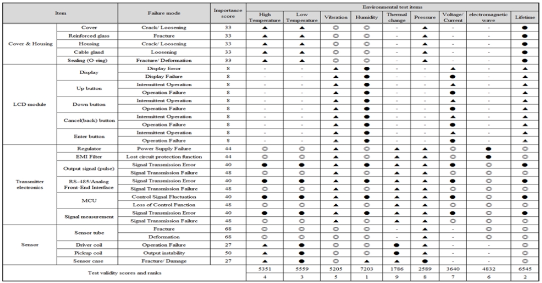
Table 8 presents the results of the first-stage QFD analysis and Table 9 summarizes the second-stage results. The first-stage evaluation was performed by examining the correlation between the failure modes of each component in the flowmeter and user requirements. The primary evaluation criteria consisted of eight technical factors, as summarized in Table 8, which represent the essential performance and environmental-reliability requirements of the system.
QFD result of flowmeter (Level 1)
QFD result of flowmeter (Level 2)
The analysis revealed that the components of the sensor section, which measure the mass flow through the Coriolis effect generated by fluid vibration, exhibited the highest importance scores. In particular, the sensor tube, driver coil, and pickup coil were identified as critical components that directly affect the measurement accuracy and output stability through their structural integrity and signal sensitivity. These components are prone to stiffness degradation and coil-insulation damage caused by repeated thermal contractions and vibrations under cryogenic conditions, leading to measurement errors and signal instabilities.
Within the transmitter, the Micro controller unit(MCU), RS-485 circuit, and output-signal circuit exhibited relatively high importance scores. These circuits are responsible for signal amplification, conversion, and transmission, and are thus vulnerable to electromagnetic interference and electrical stress, which may result in signal fluctuation or loss of the control function. In contrast, mechanical components such as the cover and housing have a limited direct influence on measurement accuracy, but may experience indirect degradation owing to vibration and moisture ingress during long-term operation.
In the second-stage QFD analysis, the importance scores obtained from the first stage were used as weighting factors to assess the relative importance of the environmental-test items related to each failure mode. The results indicated that the humidity test received the highest total score, followed by the lifetime, low-temperature, and vibration tests. This outcome reflected the operational environment of the marine flowmeter, which was continuously exposed to combined factors, such as humidity, temperature variation, and vibration. These factors can lead to insulation deterioration, signal drift, and cumulative sensor fatigue, demonstrating their significance as essential verification parameters for reliability evaluation.
Overall, the QFD analysis established a priority framework for developing environmental testing and design-validation strategies for flowmeters. In particular, humidity, lifetime, and low-temperature tests were identified as the most critical evaluation parameters for maintaining stable performance in cryogenic liquid-hydrogen environments. These findings complemented the FMEA results by providing practical guidance for improving the high-risk components identified in the earlier analyses.
4. Conclusion
This study performed a reliability evaluation of a flowmeter applied to marine liquid-hydrogen storage and supply systems under cryogenic conditions, using FMEA and QFD. The analysis focused on identifying the major failure modes of the flowmeter and deriving design improvements and environmental-validation strategies to ensure stable operation in extreme environments.
Thirty failure modes were identified in the FMEA. Among them, sensor-tube deformation was evaluated as the most critical, with an RPN value of 9, owing to the high likelihood of its occurrence from repetitive thermal contraction and vibration. Sensor-tube fractures, driver-coil operational failures, and pickup-coil output instabilities were classified in the ALARP region, indicating conditionally acceptable risks requiring appropriate inspection and maintenance management. These results highlight that both the mechanical and electronic elements of the flowmeter are crucial for maintaining measurement stability in cryogenic hydrogen environments.
The QFD analysis established a relationship between user and classification requirements and technical-design items, prioritizing environmental-test factors. The humidity test had the highest importance, followed by the lifetime, low-temperature, and vibration tests. This reflected the combined influence of humidity, temperature variation, and vibration as the major factors affecting long-term reliability. Humidity was identified as the primary cause of insulation deterioration and signal instability, emphasizing the need for waterproofing and moisture-resistant design improvements.
The integrated application of FMEA and QFD provided a systematic framework for the design verification and environmental testing of marine flowmeters. However, the risk assessment in this study was primarily based on expert judgments and proxy data owing to the current scarcity of long-term field records for marine liquid-hydrogen systems. Furthermore, this study concentrated on establishing design guidelines for the initial development phase; therefore, detailed experimental validation of specific failure mechanisms, such as sensor-tube deformation and coil-insulation degradation, is intended for future research to further validate the proposed framework. By addressing these aspects with quantitative failure mode, effects and criticality analysis (FMECA) in subsequent studies, the precision of the reliability predictions can be further enhanced. The results of this study serve as practical reference data for the development of design guidelines and reliability-assessment procedures for cryogenic hydrogen systems, thereby contributing to the development of high-reliability flowmeters capable of long-term stable performance under extreme operating conditions.
Acknowledgments
This research was supported by the Regional Innovation System & Education(RISE) program through the Jeollanamdo RISE center, funded by the Ministry of Education(MOE) and the Jeollanamdo, Republic of Korea(2025-RISE-14-002). All supports are gratefully acknowledged.
Author Contributions
Conceptualization, Y. G. Kim; Methodology, Y. G. Kim; Software, J.M. Lee; Formal Analysis, J.M. Lee; Investigation, J.M. Lee; Resources, Y. G. Kim; Data Curation J.M. Lee; Writing-Original Draft Preparation, Y. G. Kim; Writing-Review & Editing, J.M. Lee; Visualization, J.M. Lee; Supervision, Y. G. Kim; Project Administration, Y. G. Kim; Funding Acquisition, Y. G. Kim.
References
-
S. A. Alavi-Borazjani, S. Adeel, and V. Chkoniya, “Hydrogen as a sustainable fuel: Transforming maritime logistics,” Energies, vol. 18, no. 5, 1231, 2025.
[https://doi.org/10.3390/en18051231]

-
X. Zhou and J. Tao, “Hydrogen-powered vessels in green maritime decarbonization: policy drivers, technological frontiers and challenges,” Frontiers in Marine Science, vol. 12, 2025.
[https://doi.org/10.3389/fmars.2025.1601617]
- ABS, Sustainability Outlook: Carbon Neutral Fuel Pathway and Transformational Technologies, Houston, American Bureau of Shipping, 2024.
- ClassNK, ClassNK Alternative Fuels Insight, Tokyo, Nippon Kaiji Kyokai, 2025.
- DNV, Maritime Forecast to 2050, Energy Transition Outlook 2024, 2024.
-
M. Aziz, “Liquid hydrogen: A review on liquefaction, storage, transportation, and safety,” Energies, vol. 14, no. 18, p. 5917, 2021.
[https://doi.org/10.3390/en14185917]
-
L. Van Hoecke, L. Laffineur, R. Campe, P. Perreault, S. W. Verbruggen, and S. Lenaerts, “Challenges in the use of hydrogen for maritime applications,” Energy & Environmental Science, vol. 14, pp. 815–843, 2021.
[https://doi.org/10.1039/D0EE01545H]
- I. Koromila, Z. Nivolianitou, O. Aneziris, M. Gerbec, V. Maras, and E. Salzano, “A systematic literature review on safety of hydrogen as a marine fuel,” Chemical Engineering Transactions, vol. 116, pp. 727-732, 2025.
-
Y. Zhuo, C. Tu, X. Li, H. Xu, J. Wang, W. Chen, Q. Shi, Y. Lu, D. Xiao, and F. Bao, “Research on standard device of liquid hydrogen flow driven by air pressure,” Proceedings of IMEKO TC9 2022, pp. 1–6, 2022.
[https://doi.org/10.21014/tc9-2022.131]
- Institute of Measurement and Control (InstMC), Flow Measurement Requirements for Low-Carbon Fuels – Hydrogen Final Report, London, UK: InstMC, 2020.
-
X. Pei, L. Yu, X. Li, H. Xu, and X. Zhang, “Measuring tube structure optimization of Coriolis mass flowmeter with liquid hydrogen,” Flow Measurement and Instrumentation, vol. 97, 102574, 2024.
[https://doi.org/10.1016/j.flowmeasinst.2024.102574]
- D. H. Stamatis, Failure Mode and Effect Analysis: FMEA from Theory to Execution, ASQ Quality Press, 2003.
- SAE International, Potential Failure Mode and Effects Analysis(FMEA) Including Design FMEA, and Process FMEA, SAE J1379, 2021.
- U.S Department of Defense, Military Standard: Procedures for Performing a Failure Mode, Effects and Criticality Analysis(MIL-STD-1629A), 1980.
- Suwon RIC, FMEA Guideline, pp. 10-32, 2006 (in Korean).
- S. -S. Seo, H. -G. Kim, S. -J. Bae, and W. -Y. Yoon, Reliability Engineering, 3rd ed., pp. 217-230, 2020 (in Korean).
-
H. Choi, K. Seo, J. -W. Lee, and J. Lee, “MASS engine room FMEA using evidential reasoning method,” Journal of Advanced Marine Engineering and Technology, vol. 48, no. 5, pp. 359–365, 2024.
[https://doi.org/10.5916/jamet.2024.48.5.359]
-
J. Kutin, G. Bobovnik, N. Mole, M. D. Schakel, and O. Büker, “Measurement corrections for temperature effects in Coriolis mass flow meters for cryogenic, liquid hydrogen (LH₂) applications,” Measurement, vol. 237, 115155, 2024.
[https://doi.org/10.1016/j.measurement.2024.115155]
- SeoJin Instech Co., Ltd., Coriolis mass flowmeter for hydrogen applications(SCF-3000), https://www.seojin.biz/sj/sub/subProduct_view.php?idx=602&seq=1&seq2=1&seq3=&returnUrl=https://www.seojin.biz/sj/sub/subProduct.php?seq=1**seq2=1#conts¤tPage=1, , Accessed November 7, 2025.
-
R. C. Baker, Flow Measurement Handbook: Industrial Designs, Operating Principles, Performance, and Applications, Cambridge, UK: Cambridge University Press, 2016.
[https://doi.org/10.1017/CBO9781107054141]
-
T. Wang and R. C. Baker, “Coriolis flowmeters: A review of developments over the past 20 years, and an assessment of the state of the art and likely future directions,” Flow Measurement and Instrumentation, vol. 40, pp. 99-123, 2014.
[https://doi.org/10.1016/j.flowmeasinst.2014.08.015]
-
L. -H. Chen and M. -C. Weng, “An evaluation approach to engineering design in QFD processes using fuzzy goal programming models,” European Journal of Operational Research, vol. 172, no. 1, pp. 230–248, 2006.
[https://doi.org/10.1016/j.ejor.2004.10.004]
- C. N. Johnson, “QFD explained,” Quality Progress, vol. 49, no. 1, p. 40, 2016.
- ISO/IEC/IEEE, Systems and software engineering – Life cycle processes – Requirements engineering, ISO/IEC/IEEE 29148:2018, Geneva, Switzerland: ISO, 2018.
-
J. -M. Lee and Y. -G. Kim, “FMEA and QFD-based reliability evaluation of pressure sensors and transmitters for liquefied hydrogen storage systems in ships,” Journal of Advanced Marine Engineering and Technology, vol. 49, no. 4, pp. 245–255, 2025.
[https://doi.org/10.5916/jamet.2025.49.4.245]
- South Fork Instruments, Optimizing Cryogenic Hydrogen Measurement with Coriolis Meters, https://www.southforkinst.com/optimizing-cryogenic-hydrogen-measurement-with-coriolis-meters/, , Accessed November 7, 2025.
- ABS, Requirements for Hydrogen Fueled Vessels, Houston, American Bureau of Shipping, 2023.
- U.S Department of Defense, Military Standard: System Safety Program Requirements(MIL-STD-882D), 2000.