Development of current collector using one-finish compounding cold-forging technology for x-EV battery cells
Copyright © The Korean Society of Marine Engineering
This is an Open Access article distributed under the terms of the Creative Commons Attribution Non-Commercial License (http://creativecommons.org/licenses/by-nc/3.0), which permits unrestricted non-commercial use, distribution, and reproduction in any medium, provided the original work is properly cited.
Abstract
The technological developments of this study represent a core component of x-EV battery cells. In recent years, the development of x-EV-component technology has become very important in the automobile industry because of the reduction in energy resources and environmental problems. An EV battery pack has several modules composed of numerous pouch-type cells. The target product for this technological development is a current collector, which is a core component of a cell. A current collector consists of a positive electrode and negative electrode, and serves to store and release electrochemical energy. The elemental materials used for the anode and cathode current collectors are aluminum and copper, respectively. Mass-production press technology is required to respond to the demand for current-collector parts. Therefore, this study presents a near-net-shape one-finish compounding cold-forging method to reduce manufacturing costs and mass-production defects.
Keywords:
X-EV, Current Collector, One-finish compounding, Cold forging, Forming simulation, Optimization1. Introduction
The world has recently transitioned to a carbon-neutral society in response to climate change. Accordingly, we are currently developing a high-battery x-EV as an eco-friendly vehicle alternative. In particular, considerable effort is being made to develop high-quality, flawless mass-production technology for core parts to secure an advantage in terms of increasing demand and price competitiveness.
The target product for this technological development is a current collector, which is a core component of battery cells [1]. A current collector consists of a positive electrode and negative electrode, and serves to store and release electrochemical energy. The raw materials of the positive- and negative-electrode current collectors are aluminum and copper, respectively [2]. The demand for this technological-development product is expected to exceed 12,000,000 EA annually; therefore, developing a technology that can produce the expected product quantity and reduce manufacturing costs is essential. Figure 1 shows the positions of the current collectors of the positive and negative electrodes of a battery cell.
2. Current-Collector Production Process
2.1 Current Collector
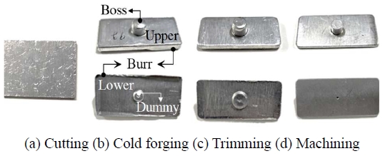
The current collector of an electric vehicle is an important device that transfers electrical energy from an external power source to the vehicle. Because stable and efficient power transfer is essential during driving, shape accuracy is required. The shape of the current collector, which is the part to be studied, is shown in Figure 2. It has a rectangular shape with a rounded center, and the dimensions of the positive and negative parts are the same. During forging, a protruding boss portion and dummy portion are formed on the upper and lower surfaces, respectively. After forging, the boss part must be machined, and the dummy part and burr must be removed.
2.2 General Production Process
Most forging companies produce current collectors using traditional production methods because they supply them in small amounts when needed. During the production process, cold forging and trimming are performed after the raw Al materials are cut, as shown in Figure 3. The upper boss should be machined after the forging process, and mechanical processing should be performed after the trimming process to remove the lower dummy and side burr.
The existing method increases the production cost of the parts. Because the demand for battery cells will increase rapidly in the future, production and price competitiveness cannot be secured if they are produced using existing methods.
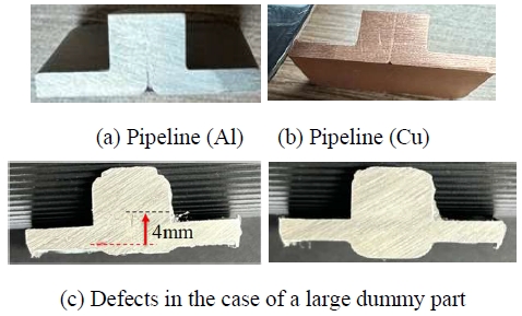
In addition, a pipe is generated in the boss part because of the failure to properly consider the metal-flow characteristics of aluminum when forming the existing process (Figure 4(a), (b)). This is because of the upward metal flow when forming the boss part. To prevent this, the dummy part must be made in the opposite direction [3].
However, if the dummy part is too small, an internal pipe is formed; if it is too large, problems such as noise generation and tool-life reduction occur (Figure 4(c), (d)).
3. One-finishing Compound Forging
3.1 Concept of One-Finishing Compound Forging
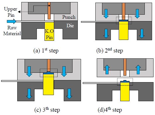
In this study, we propose a semi-finishing compound cold-forging method based on a semi-finishing combination to prevent mass-production defects in current collectors. The core of the proposed method is to perform the raw-material cutting, forging, and trimming processes simultaneously. Then, the final current collector is produced by machining the boss and lower dummy parts. The concept of the one-finishing compound-forging method is shown in Figure 5.
When the raw material is added, the upper and lower tools then descend, and the material is cut. The upper pin is maintained at a constant height, and the forging process is performed by lowering the upper and lower tools. Finally, the material is extracted. This process is performed continuously, and a side burr is hardly generated by semi-structured forming without a trimming process.
In the existing process, a cutter and two sets of dies are required; however, in the development process, only one die set can be formed. However, to mass-produce high-quality parts without defects with the proposed method, the flow characteristics of the material compared to the weight of the input material must be understood. As shown in Figure 6, the flow direction of the material varies greatly with and without dummy parts. Therefore, in this study, the optimal dummy-part shape was determined by applying the material-flow control method based on the weight of the input material [4]-[6].
3.2 Dummy Part of Current Collector
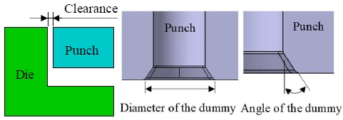
In this study, to apply the net-shape cold-forging method, a reverse design was performed by setting the shape of the final forging to 4 mm. As described above, the shape determination of the dummy part is important for forming the current-collector part. As shown in Figure 7, the ➀ outer diameter of the dummy part, ➁ height of the dummy part, and ➂ angle of the dummy part are important variables that determine the dummy shape.
4. Design of Dummy Part
Forming analysis was performed to determine the optimal shape of the dummy part that could be formed without defects. The objective function included the forming load, contact areas of the boss and dummy parts, and height of the boss part. Under the filling conditions inside the punch and die, a lower forming load is better. The boss part satisfied the shape requirements if it was 6.5 mm or greater.
4.1 Design Parameter and Orthogonal Array
In this study, the design variables that determined the shape of the dummy part were the clearance, outer diameter of the dummy part, and angle of the dummy part (Figure 8). The set variables were those that had an important influence on burr generation and the metal flow of the boss and dummy parts.
The level of clearance was set to 0.01, 0.02, and 0.03 mm, and the outer-diameter levels of the dummy part were set to Φ 7.5, Φ 8.0, and Φ 8.5. The dummy-part angles were set to 50°, 55°, and 60°. The height of the dummy part was analyzed under the same conditions. In this study, the FE (Finite Element) simulation was performed using an L9 orthogonal-arrangement table.
4.2 FE-Simulation
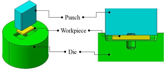
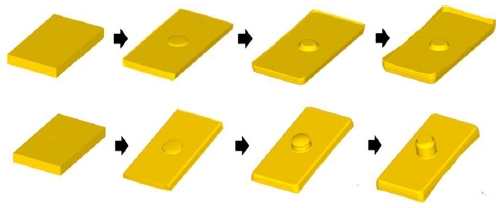
To perform a forming analysis on the dummy shape, three-dimensional modeling was performed on the tools and material shapes, as shown in Figure 9. The analysis was conducted using a 1/4 cross-section. Figure 10 shows the forming process for the boss and dummy parts. The forming velocity was 1 m/s.
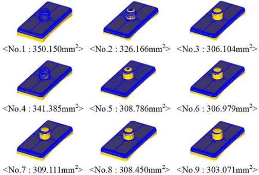
Table 3 lists the analysis results based on the orthogonal-arrangement table. Regarding the forming load, No. 1 was the highest and No. 9 was the lowest. The contact area of the boss part used to determine the filling degree inside the tool was the highest for No. 1 and lowest for No. 9. The contact area of the dummy part was similar in all cases. The boss part was high in No. 1, No. 2, No. 4, and No. 5, and the lowest in No. 9. However, in all cases, satisfactory results of 6 mm or more could be obtained.
In all the cases, no pipeline, which is a dummy defect, occurred. However, the larger the difference in the contact area of the boss part based on the design variable and the larger the contact area, the higher was the forming load. This was a natural result because the inside of the boss part was filled. That is, when the clearance, outer diameter of the dummy part, and angle of the dummy part were small, the inside of the tool was completely filled by quickly filling the dummy part, and the metal flow proceeded to the upper boss part. However, this is unfavorable for the life of the tool because of the rapid increase in the forming load.
4.3 Application of ANN
In this study, an artificial neural network (ANN) was applied to analyze the effect of the shape of the dummy part on the die contact area and forming load of the boss part [7]. The influence of the design parameters on the die contact area of the boss part was analyzed by training the orthogonal array table in Table 3 (Figure 13).
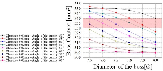
The results obtained after training the neural network are shown in Figure 14. As shown in the graph, as the clearance increased, the contact with the boss part tended to decrease. Moreover, as the outer diameter of the boss part increased, the contact of the boss part tended to decrease. Considering mechanical processing, if the contact area of the boss part was 330 mm2 or more, the dimensional requirements of the boss part could be satisfied after forging. As the contact area of the boss part increases, the forming load increases.
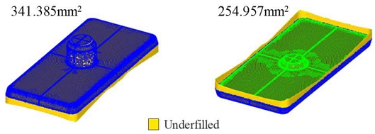
Therefore, considering the life of the tools, a clearance of 0.02 mm, boss-part outer diameter of 7.8 mm, and dummy-part angle of 50° are advantageous. In this study, an analysis was performed on this case, as shown in Figure 16. The analysis results were similar to the predicted results for the contact area of the dummy part, and the forming load was good at 150 t.
4.4 Field Test
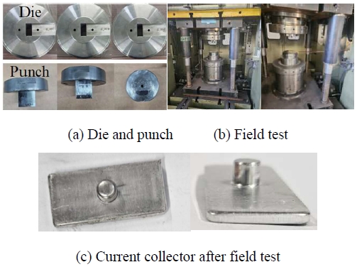
Based on the forming analysis and neural-network prediction results, a punch and die were produced using a clearance of 0.02 mm, an outer diameter of 7.8 mm, and a dummy angle of 50°. Figure 16(a) shows the prepared punch and die shape, and Figure 16(b) shows the field test. After the final test, the shape of the current collector after the forging process is shown in Figure 16(c). The test results showed that a good product shape was obtained, and no defects, such as pipelines or incomplete filling, occurred.
4. Conclusion
In this study, a mass-production press method was proposed to respond to the demand for current collectors, which are a core component of the battery cells of x-EVs. The proposed method was a near-net shape one-finish compounding cold-forging method, and the dummy-part shape was designed based on the design variables. Consequently, the diameter, angle, and clearance of the dummy part were identified, and the optimal combination of design variables applicable to the field was determined through the application of neural networks. If the proposed forging method is applied, the mass production of various electric-vehicle parts may be developed in the future. However, to verify the reliability and mass-production applications of this study, additional tests and FE-simulations should be performed in future studies.
Author Contributions
Conceptualization, M. Park and D. Kim; Methodology, D. Kim; Software, M. Park; Validation, M. Park and D. Kim; Formal Analysis, M. Park and D. Kim; Investigation, M. Park; Resources, D. Kim; Data Curation, M. Park; Writing—Original Draft Preparation, D. Kim; Writing—Review & Editing, D. Kim; Visualization, D. Kim; Supervision, D. Kim; Project Administration, D. Kim; Funding Acquisition, D. Kim.
References
-
K. Y. Cho, S. H. Hong, J. Kwon, H. Song, S. Kim, S. Jo, and K. S. Eom, “Effects of a nanometrically formed lithiophilic silver@copper current collector on the electrochemical nucleation and growth behaviors of lithium metal anodes,” Applied Surface Science, vol. 554, pp. 685-293, 2021.
[https://doi.org/10.1016/j.apsusc.2021.149578]

-
N. V. Raghavaiah and G. N. Srinivasulu, “Experimental investigations on performance of passive direct methanol fuel cell using Nickel-201 and brass current collector materials,” Chemical Papers, vol. 76, no. 7, pp. 4581-4595, 2022
[https://doi.org/10.1007/s11696-022-02200-5]

-
K. H. Ann, J. H. Kang, S. J. Heo, T. S. Shin, and H. Y. Cho, “Multistage cold forging process design of Al6082 considering forming limit,” Journal of The Korean Society of Manufacturing Process Engineers, vol. 19, no. 9, pp. 93-99, 2020.
[https://doi.org/10.14775/ksmpe.2020.19.09.093]

- S. J. Park, M. S. Joun, B. M. Kim, and D. H. Kim, “Influence of punch motion on the formability of a cup with boss in backward extrusion,” International Symposium on Green Manufacturing and Application, p. 193, 2018.
-
S. J. Park, S. G. Lee, and D. H. Kim, “Studies on precision bending of motor spring,” Transactions of Materials Processing, vol. 25, no. 6, pp. 366-372, 2016 (in Korean).
[https://doi.org/10.5228/KSTP.2016.25.6.366]

-
J. G. Eom, S. W. Jung, and M. S. Joun, “Metal forming simulation with emphasis on metal flow lines and its applications,” Transactions of Materials Processing, vol. 22, no. 6, pp. 323-327, 2013 (in Korean).
[https://doi.org/10.5228/KSTP.2013.22.6.323]

- D. H. Kim, D. J. Kim, D. C. Ko, B. M. Kim, and J. C. Choi, “Design methodology of preform in multi-stage metal forming processes considering workability,” Transactions of the Korean Society of Mechanical Engineers A, vol. 22, no. 9, pp. 1615-1624, 1998 (in Korean).


