A study on the structural vibration of the main engine of a fishing boat
Copyright © The Korean Society of Marine Engineering
This is an Open Access article distributed under the terms of the Creative Commons Attribution Non-Commercial License (http://creativecommons.org/licenses/by-nc/3.0), which permits unrestricted non-commercial use, distribution, and reproduction in any medium, provided the original work is properly cited.
Abstract
Structural vibrations significantly affect the reliability, efficiency, and safety of engines. Excessive vibrations pose a threat to component integrity, accelerating wear on essential parts such as pistons and crankshafts. Accordingly, controlling structural vibrations is imperative for enhancing engine efficiency by minimizing energy losses and optimizing fuel consumption. This study examines the structural vibration of a 588 kW 4-stroke diesel engine installed on a tonnage fishing boat. Analysis revealed a natural vibration frequency of approximately 118 Hz, resulting in resonance at 1700–1800 rpm by the 4th order. The vibration level exceeded the acceptable criteria. A novel solution for installing additional reinforcing bars to secure the engine to the walls and floor of the engine room is suggested to improve the vibration behavior of the main engine.
Keywords:
Structural vibration, Controlling vibrations, 4-stroke diesel engine, Natural vibration, Resonance1. Introduction
In the maritime industry, research indicates that approximately 40 percent of incidents are related to engine malfunctions [1]-[3]. Appropriate repair and maintenance of ship equipment play an important role in reducing maritime disasters and improving marine safety [4]. In general, there are three types of maintenance: They are failure, protective, and predictive. Failure maintenance is related to the overhauling of the entire engine. Protective maintenance is performed according to the engine manufacturer recommendations. Predictive maintenance is a special type of maintenance that allows the diagnosis of engine health without invasive intervention. Structural vibration analysis is an effective predictive maintenance method to identify errors and detect fault sources [5][6]. Structural vibrations create an initial force or a continuous excitation force acting on an object. When an object vibrates under the influence of an initial force, it is a free vibration. Over time, the vibration amplitude diminishes due to the loss of acting energy, and the object stops moving. A simple example is a spring vibrating under an initial excitation force. It vibrates with a decrease in vibration amplitude and then stops when the energy generated by the initial excitation force equals zero.
By contrast, forced vibrations occur when the structure is continuously subjected to excitation forces. When the frequency of an excitation force coincides with the frequency of the structure, the vibration amplitude can be amplified significantly and resonance appears [7]. For instance, vibrations occur because of excitation forces during engine operation. Excessive vibration levels contribute to material fatigue and lead to excessive wear of moving parts in marine diesel engines, such as pistons and crank-shafts [8]. In the modern ship design stage, calculating vibration excitation is essential to avoid vibration resonance during engine operation. The final purpose of this calculation is to keep the natural frequency of the propulsion system away from the dangerous excitation frequency [9].
Structural vibration prediction is necessary to ensure the efficient operation of machinery and enhance its safety and lifespan. Machinery often operates under various load conditions for a long time, which may induce an imbalance in the shafts and a high excitation force. Through accurate predictions of these vibrations, engine damage can be avoided and repair costs can be reduced.
Furthermore, vibration prediction in the machinery design process offers many advantages, including improved energy efficiency, reduced fuel consumption, and extended longevity [10].
Structural vibrations can be characterized by displacement, velocity, or acceleration, with each parameter representing a measurement method. The choice of measurement depends on the frequency range of interest, where displacement is used for low-frequency vibrations, velocity for medium-frequency vibrations, and acceleration for high-frequency vibrations [11]. To obtain these parameters, vibration sensors are attached to the measurement objects. In general, velocity is used to assess the conditions of machinery and motors [12]. Displacement is applied to machinery and systems with slow-moving parts to detect imbalances and misalignments [13]. Acceleration plays a role in providing instant vibration analysis and is essential for identifying issues such as bearing faults or misalignments that occur at higher frequencies [14].
Currently, various methods are employed to analyze structural vibration, including fast Fourier transform (FFT) [15], fuzzy logic, Wigner–Ville distribution [16][17], and wavelet transform [18]-[21]. However, these methods require a certain level of understanding of structural vibrations. This study aims to simplify vibration analysis methods and assist engineers and operators in gaining a comprehensive overview of the vibration analysis of 4-stroke main engines.
In this study, experiments and field research were conducted on small fishing vessels to prevent the potential deterioration of the main engine and shaft system due to structural vibrations. Based on this phenomenon, increasing structural vibrations were observed at certain engine operating speeds. Furthermore, torsional vibration was examined to determine whether it contributed to structural vibration. The structural vibration levels were evaluated in terms of the vibration velocity according to two standards: “Vibration Class” by Det Norske Veritas (DNV) [22] and ISO 20816-9:2020 for the mechanical vibration of gear units [23].
2. Experiment Setup
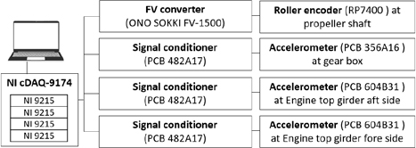
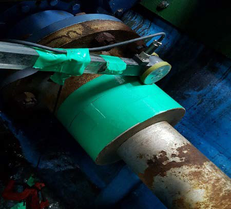
The details of the main engine are listed in Table 1. A schematic of the structural and torsional vibration measurements in this research is presented in Figure 1. An anti-slip roller encoder (type RP-7400, ONO SOKKI) was installed on the propeller shaft to measure the angular velocity of rotation, as shown in Figure 2. This sensor could perform at 0.01 m/min (1200 pulses/revolution).
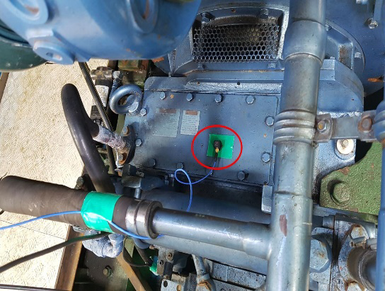
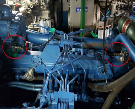
To convert the frequency signal from the roller encoder into a voltage signal proportional to the angular velocity, a high-speed frequency-to-voltage converter (type FV-1500, ONO SOKKI) was used. It has a high-speed response for a wide frequency range of 0.2 Hz to 320 kHz. A triaxial accelerometer (PCB 35A16, Piezotronics) was attached to the gearbox, illustrated in Figure 3. Two triaxial accelerometers (PCB 604B31, Piezotronics) were installed at the engine's top girder aft and fore sides, as displayed in Figure 4. All these triaxial accelerometers have a nonlinearity of less than 1% in the frequency range from 0.5 to 5000 Hz. A signal conditioner (PCB 482A17, Piezotronics) supplied power and picked up the signal from the accelerometers. The data acquisition (DAQ) (cDAQ-9174 and NI-9215, National Instruments) converts analog signals to digital signals, enabling the computer to record the vibration data.
Measurements were performed continuously across the entire engine speed range. The engine speed was gradually increased in increments, and each speed was maintained for 30 s to ensure steady-state conditions for data recording.
3. Methodology
3.1 Relationship between Vibration Velocity and Vibration Acceleration
In this experiment, accelerometers were used to measure the structural vibrations. However, the vibration signal should be assessed in terms of vibration velocity to align with the criteria specified in the standards. The relationship between the velocity and acceleration of the vibration is expressed by the following equations:
| (1) |
| (2) |
with
| (3) |
where
= A: Amplitude of vibration velocity (m/s)
= Aω: Amplitude of vibration acceleration (m/s2)
f : Frequency of vibration (Hz)
ω: Circular frequency (rad/s)
t : Time (s)
φ: Initial phase of vibration (rad)
From (1)-(3), the transformation from the vibration acceleration amplitude to the vibration velocity is determined by
| (4) |
For example, if the vibration acceleration at 60 Hz has an amplitude of 2 m/s², the vibration occurring at that frequency domain will be converted into a velocity amplitude of 5.3 × 10⁻³ m/s by (4).
The signal processing procedure was as follows:
- o The vibration waveform was recorded in the time domain.
- o FFT was applied to transform the time-domain signal to a frequency domain.
- o In the frequency domain, the obtained vibration amplitude of the acceleration was translated to that of the vibration velocity using (4).
3.2 Harmonic Order Analysis
Harmonic order analysis is an effective method for accurately evaluating the level of vibration and identifying its sources. When the rotational frequency of the shaft corresponds to the vibration frequency excited by the engine operation, the relation can be determined as follows:
| (5) |
Order numbers are typically integer numbers, such as 1, 2, 3, ...n. For example, a four-blade propeller creates a vibration with four cycles per propeller revolution, corresponding to the 4th harmonic order. Half orders (0.5, 1.5, etc.) are commonly observed in 4-stroke diesel engines where a working cycle takes place over two shaft revolutions [24].
The harmonic order amplitude is typically presented as a peak value. However, some standards assess the vibration amplitude using the root mean square (RMS) values, which characterize the vibration energy. An RMS value is equivalent to 1⁄√2 of the corresponding peak value.
4. Results and Discussion
4.1 Structural Vibration
The ISO 20816-9:2020 standard is used to assess the level of structural vibration in the gearbox. Accordingly, for the engine with a nominal output of 588 kW, as shown in Table 1, the vibration limit for each vibration component is 12.5 mm/s for RMS values, corresponding to 17.7 mm/s in peak values. In this study, all vibration levels in the figures are presented as peak values.
Figure 5 shows the measurement results for the vibration of the gearbox. The 4th harmonic order vibration level excited by the combustion process of eight cylinders was the highest. Subsequently, in the transverse and vertical directions, the vibration level of the 4th harmonic order was significantly higher than that in the longitudinal direction. However, this vibration level is still much lower than the limit of 17.7 mm/s. This demonstrates that the vibration level at the gearbox satisfied the limitation standard and was acceptable. No issues related to structural vibrations affecting the gearbox of the main engine were observed.
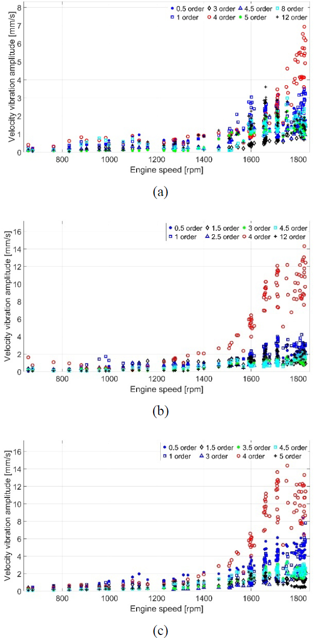
Vibration velocity at the gearbox: (a) longitudinal direction; (b) transverse direction; (c) vertical direction
On the engine side, the DNV AS standard was applied to evaluate the vibration levels. Following Table 1 and this standard, the engine had a maximum continuous rating speed of 1950 rpm and was resiliently mounted; therefore, the vibration limit was set at 25 mm/s. Figure 6 shows the results of the vibration measured on the aft side of the engine. In the longitudinal and vertical directions, the vibration level of the 4th harmonic order was the highest. However, these were less than 25 mm/s, satisfying the aforementioned standards. By contrast, in the transverse direction, the vibration level of the 4th order was much higher than the above limit.
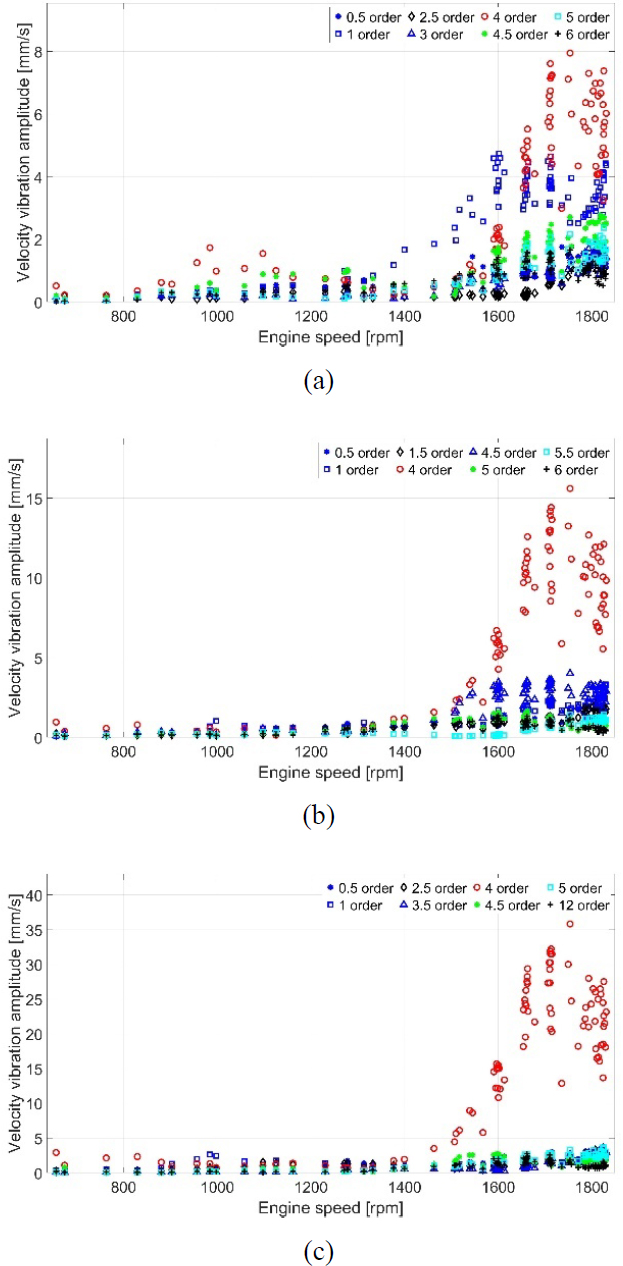
Vibration velocity on the engine top girder aft side: (a) longitudinal direction; (b) vertical direction; (c) transverse direction
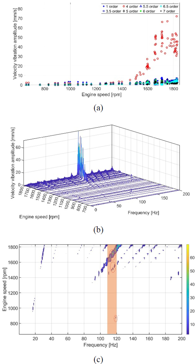
The vibration velocity of the aft side of the engine top girder in the transverse direction was determined from the waterfall and contour map plots exhibited in Figure 7. The highest vibration level appeared within the engine speed range of 1700–1800 rpm at a frequency of approximately 118 Hz, corresponding to the 4th harmonic order. Moreover, within the same frequency range, resonance also appeared at the 5th harmonic order between 1400 and 1600 rpm and at the 8.5th harmonic order in the range of 800–1000 rpm. This suggests that the propulsion system has a natural vibration frequency of approximately 118 Hz. These resonances were within the frequent operation zone of the engine.
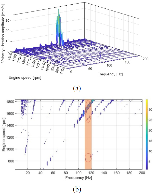
Vibration velocity on the engine top girder aft side in the transverse direction: (a) waterfall; (b) contour map
At the fore side of the engine top girder, the resonances appeared to be similar to those observed at the engine top girder aft side. In the transverse direction, the vibration level at the 4th order significantly exceeded the limit specified in the DNV AS standard. The natural frequency was approximately 118 Hz inside the frequent operation zone of the engine, described in Figure 8. Continuous operation under these conditions can be hazardous to moving parts such as pistons and crankshafts, resulting in wear, tear, and potential cracking.
4.2 Torsional Vibration
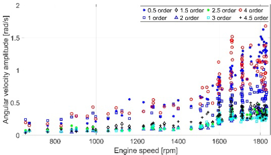
In vibration analysis, torsional vibration is one of the causes of large structural vibrations when an engine is running. Therefore, torsional vibration analysis of the propeller shaft was conducted. Typically, if resonance occurs during torsional vibration, the angular velocity vibration of the shaft will experience significant fluctuations. Figure 9 indicates that the angular velocity vibrations of all harmonics over the entire engine speed range showed no remarkable fluctuations. The angular velocity amplitude of 4th order was negligible, and resonance did not occur in the speed range of 1700–1800 rpm. This was not the same as the vibration level on the 4th order of the engine top girder sides. This proved that torsional vibration was not a source of excessive structural vibration.
4.3 Discussion
The analysis revealed a natural frequency of structural vibration of approximately 118 Hz, leading to resonance at the 4th harmonic order within the 1700–1800 rpm range. The vibration levels exceeded the acceptable criteria. To address this issue, reducing the vibration excitation forces or altering the natural frequency to shift the resonance out of the frequent operating range of the engine is necessary.
First, the resonance can be mitigated by minimizing the vibration excitation forces through an engine overhaul:
- o Perform a comprehensive inspection and maintain the engine, including checking corrosion-prone rotating parts such as the crankshaft, connecting rod, and piston ring. If these parts are damaged, they must be replaced.
- o Tighten the bolts connecting the engine bedplate to the engine room floor.
Second, the natural frequency of the propulsion system should be adjusted to shift the resonance beyond the frequent operating range of the engine. The system can be simplified to a mass-elastic model, including masses (m) and springs (k), as shown in Figure 10.
The natural frequency of an entire system can be altered by modifying the mass or stiffness of any component. The relationships among the natural frequency, mass, and stiffness of a component are as follows:
| (6) |
where
fn: Natural frequency (Hz)
k: Stiffness (N/m)
m: Mass (kg)
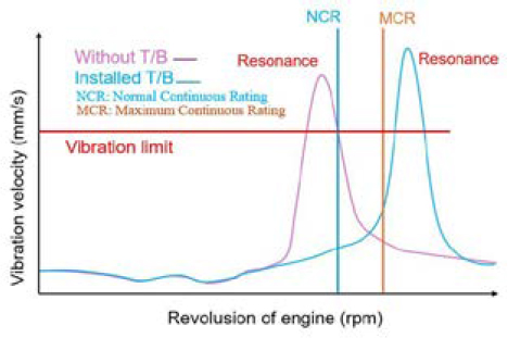
As (6) shows, stiffness and natural frequency have a direct relationship, whereas mass and natural frequency have an inverse relationship. Thus, the natural frequency can be reduced by either increasing the mass or decreasing the stiffness. However, a decrease in the natural frequency may not completely solve this problem, as the resonance may still be within the engine’s frequent operation range. The natural frequency can be increased by increasing the stiffness or decreasing the mass of the components in the propulsion system. The mass can be reduced by removing the unimportant parts. Nevertheless, few components can be removed from this engine. Another method is to increase the stiffness. This can be accomplished via two methods. In the first method, the main engine piping system, such as the fuel pipe, cooling water pipe, lubricating oil pipe, and exhaust gas pipe, can be replaced with a new type of higher-stiffness material [25]-[28]. This traditional method has been applied to many merchant ships. In the second method, additional bars can be installed on the wall and floor of the engine room to reinforce the engine. This is a new method with an operating principle similar to that of top-bracing systems, which are usually applied in large two-stroke main engines. As previously discussed, resonance leads to amplified vibrations. The purpose of using top bracing is to move the resonance away from the engine's frequent operation zone, thereby reducing the vibration level, as shown in Figure 11.
Installing these bars has the following several benefits:
- o Increasing stiffness: The entire structure is protected from the dynamic forces created by the engine operation.
- o Load transfer: The installed bars distribute the dynamic load throughout the engine structure. This prevents stress concentration at one position, which leads to excessive vibration or structural damage.
- o Prevention of structural deformation: The bars provide additional support for the engine structure. This is essential for maintaining the alignment of the rotating components during engine operation under different load conditions.
5. Conclusion
This study investigated the structural vibrations of a 4-stroke high-speed diesel engine propulsion system on a fishing boat using measurements obtained during an actual sea trial. The purpose was to identify the cause of the intensive structural vibrations observed at specific engine operating speeds and propose measures to improve vibration performance. The vibration levels were assessed according to ISO 20816-9:2020 for the gearbox and the DNV AS standard for the main engine. The conclusions are as follows:
- (1) Order-tracking analysis revealed that the most intense vibration was at the 4th order generated by the working process of the eight cylinders.
- (2) The angular velocity fluctuation measured on the propeller shaft was not significant. This indicated that the torsional vibration was not a source of excessive structural vibration.
- (3) Although the vibration levels at the gearbox were within these limits, the vibrations measured on the top girders of the engine exceeded the allowable criteria. A natural frequency of approximately 118 Hz was identified, resulting in a vibration resonance in the range of 1600–1800 rpm by the 4th order. This is the primary source of excessive vibrations. Reducing the level of vibration resonance or shifting the resonance speed away from the operating range of the main engine is critical.
- (4) The first solution involves comprehensive inspection and maintenance of the main engine. This can help reduce the excitation force of the 4th harmonic order and, consequently, lower the vibration at resonance.
- (5) The second solution focused on adjusting the natural frequency of the system. Installing additional bars connecting the engine body to the engine room is recommended. These bars function as top bracing devices, increasing the stiffness of the engine's support structure and thereby increasing the natural frequency of the system.
We conducted a study based on classification rules and international standards and presented an appropriate solution to the problem. After the proposed solutions are implemented, their structural vibration performances should be re-examined to confirm their effectiveness. The results will be presented in a future study.
Acknowledgments
This research was supported by the 'Development of Autonomous Ship Technology(20200615)' funded by the Ministry of Oceans and Fisheries(MOF, Korea) and by the National Research Foundation of Korea(NRF) grant funded by the Korea government(MSIT) (No. NRF-2021R1F1A1047115).
Author Contributions
Conceptualization, H.N. Truong, J.-W. Lee, Q.D. Vuong and J-U.Lee; Methodology H.N. Truong; Software, H.N. Truong, Q.D Vuong; Validation, H.N. Truong, Q.D Vuong and J-U. Lee; Formal Analysis, H.N Truong; Investigation, H.N. Truong, Q.D Vuong and J-U. Lee; Data Curation, H.N. Truong, Q.D Vuong; Writing—Original Draft Preparation, H.N. Truong, Writing—Review & Editing, Q.D Vuong, J-U. Lee; Visualization, H.N. Truong; Supervision Q.D Vuong, J-U.Lee; Project Administration, J-U. Lee; Funding Acquisition, J-U. Lee.
References
-
C. Kandemir, O. Soner, and M. Celik, “Proposing a practical training assessment technique to adopt simulators into marine engineering education,” WMU Journal of Maritime Affairs, vol. 17, no. 1, pp. 1-15, 2018.
[https://doi.org/10.1007/s13437-018-0137-4]

- EMSA, Annual overview of marine casualties and incidents, Lisbon, Portugal: European Maritime Safety Agency, 2015.
-
R. Islam, H. Yu, R. Abbassi, V. Garaninya, and F. Khan, “Development of monograph for human error likelihood assessment in marine operations,” Safety Science, vol. 91, pp. 33-39, 2017.
[https://doi.org/10.1016/j.ssci.2016.07.008]

-
E. Akyuz and E. Celik, “A modified human reliability analysis for cargo operation in single point mooring (SPM) off-shore units,” Applied Ocean Research, vol. 58, pp. 11-20, 2016.
[https://doi.org/10.1016/j.apor.2016.03.012]

-
A. Kumar, P. Sathujoda, and N. A. Bhalla, “Vibration signal analysis of a rotor-bearing system through wavelet transform and empirical mode decomposition,” IOP Conference Series: Materials Science and Engineering, vol. 1248, 012027, 2022.
[https://doi.org/10.1088/1757-899X/1248/1/012027]

-
A. Umbrajkaar, A. Krishnamoorthy, and R. B. Dhumale, “Vibration analysis of shaft misalignment using machine learning approach under variable load conditions,” Shock and Vibration, 2020.
[https://doi.org/10.1155/2020/1650270]

- W. T. Thomson, Theory of Vibration with Applications, 5th Edition: Prentice Hall, 1998.
-
G. Madhukar, S. Boosi, Z. A. Adhoni, K. A. Bhaskar, A. V. Naik, “A machine learning based methodology for fault diagnosis in rotating machine,” In Proceedings of the 2023 IEEE International Conference on Integrated Circuits and Communication Systems (ICICACS), Raichur, India, 24–25 February, pp. 1-5, 2023.
[https://doi.org/10.1109/ICICACS57338.2023.10100301]

- Tienhaara, Guidelines to engine dynamics and vibrations, Wärtsilä, NSD Switzerland Ltd, 2004.
-
J. S. Bendat and A. G. Piersol, Random Data: Analysis and Measurement Procedures: Wiley, 2010.
[https://doi.org/10.1002/9781118032428]

- Lifetime Reliability, Fundamentals of Vibration Measurement and Vibration Analysis Explained: Lifetime Reliability Solutions, 2021. Available: Lifetime Reliability.
-
J. Fraden, Velocity and Acceleration. In: Handbook of Modern Sensors: Springer, New York, 2010 [Online].
[https://doi.org/10.1007/978-1-4419-6466-3_8]

- Wilcoxon Sensing Technologies, Measuring Displacement Using Accelerometers, 2018.
- VRU Vibration Research, Velocity and Displacement Sensors for Vibration Control, June 10, 2022. Available online: https://vru.vibrationresearch.com, .
-
M. J. Corinthious, A fast fourier transfom for high-speed signal processing, IEEE Transactions on Computers, vol. C-20, no. 8, pp. 843-846, 1971.
[https://doi.org/10.1109/T-C.1971.223359]

-
M. Bai, J. Huang, M. Hong, and F. Su, “Fault diagnosis of rotating machinery using an intelligent order tracking system,” Journal of Sound and Vibration, vol. 280, no. 3-5, pp. 699-718, 2005.
[https://doi.org/10.1016/j.jsv.2003.12.036]

-
J. D. Wu, C. W. Huang, R. Huang, “An application of a recursive Kalman filtering algorithm in rotating machinery,” NDT & E International, pp. 411-419, 2004.
[https://doi.org/10.1016/j.ndteint.2003.11.006]

-
C. Changzheng, S. Changcheng, Z. Yu, and W. Nan, “Fault diagnosis for large-scale wind turbine rolling bearing using stress wave and wavelet analysis,” ICMES 2005 Processing of the Eighth International Conference on Electrical Machines and Systems, pp. 2239-2244, 2005.
[https://doi.org/10.1109/ICEMS.2005.202966]

-
J. Lin and L. Qu, “Feature extraction based on Morlet wavelet and its application for mechanical diagnosis,” Journal of Sound and Vibration, vol. 234, no. 1, pp. 135-148, 2000.
[https://doi.org/10.1006/jsvi.2000.2864]

-
S. Prabhakar, A. R. Mohanty, and A. S. Sekhar, “Application of discrete wavelet transform for detection of ball bearing race faults,” Tribology International, vol. 35, no. 12, pp. 793-800, 2002.
[https://doi.org/10.1016/S0301-679X(02)00063-4]

-
P. W. Tse, W. Yang, and H. Y. Tam, “Machine fault diagnosis through an effective exact wavelet analysis,” Journal of Sound and Vibration, vol. 277, no. 4-5, pp. 1005-1024, 2004.
[https://doi.org/10.1016/j.jsv.2003.09.031]

- ISO 208169-2:2020: Mechanical vibration – Measurement and evaluation of machine vibration “ Part 9: Gear units”, Published January 2020.
- Det Norske Veritas AS, Rules for classification of Ship, Section 2: Vibration Criteria, 2011.
- Lloyd's Register, Ship Vibration and Noise Guidance Notes, Revision 2.1, 2006.
-
T. Hu, X. Ding, L. Shen, and H. Zhang, “Improved adaptive growth method of stiffeners for three-dimensional box structures with respect to natural frequencies,” Computers & Structures, vol. 239, 2020.
[https://doi.org/10.1016/j.compstruc.2020.106330]

-
P. Gao, J. Zhai, F. Z. Qu, and Q. Han, “Vibration and damping analysis of aerospace pipeline conveying fluid with constrained layer damping treatment,” Journal of Aerospace Engineering, vol. 232, no. 8, 2018.
[https://doi.org/10.1177/0954410017692367]

-
H. Sui and W. Niu, “Branch-pipe-routing approach for ships using improved genetic algorithm,” Frontiers of Mechanical Engineering, vol. 11, pp. 316-323, 2016.
[https://doi.org/10.1007/s11465-016-0384-z]

- L. Xia, Q. Xia, X. Huang, et al., A Stiffener Layout Design Method for Vibration Reduction in a Wide Frequency Band: SpringerLink, 2018.

