Inductive signal couplers for a wire feeder mobile gateway in shipyard-IoT
Copyright © The Korean Society of Marine Engineering
This is an Open Access article distributed under the terms of the Creative Commons Attribution Non-Commercial License (http://creativecommons.org/licenses/by-nc/3.0), which permits unrestricted non-commercial use, distribution, and reproduction in any medium, provided the original work is properly cited.
Abstract
This study proposes a networking solution for Internet of Things (IoT) implementation in shipyards with poor fixed or wireless communication infrastructure. Adding non-contact power line communication (PLC) functionality to the wire feeder and single cable allows them to serve as a mobile gateway. Considering the high current variations in welding cables, the electromagnetic characteristics of the inductive signal coupler are simulated using COMSOL software, the magnetic flux density distribution is visualized, and conditions for magnetic flux saturation are proposed. In the magnetic flux saturation state, the induced electromotive force in the secondary coil decreases, thereby significantly reducing the communication bandwidth. The fabricated signal coupler maintains a 0.2 mm air gap, securing a bandwidth of > 15 Mbps even at line currents of 90 A.
Keywords:
Internet of Things, Power line communication, Inductive signal coupler, Ferrite core, Wire feeder1. Introduction
The Internet of Things (IoT) refers to a network of physical objects, such as sensors, machines, automobiles, and buildings, which interact and collaborate to achieve common goals. The fusion of power line networks and IoT technologies drives industrial innovation [1][2]. When the infrastructure for data networks is lacking or insufficient, the IoT combined with power networks can extend beyond smart homes to smart cities and factories. Power line communication (PLC) is a technology for data transmission via existing power grids and has been studied for use in trains [3], ships [4], electric vehicles [5], and other moving objects by utilizing their distributed wires.
In shipyards, there is a growing focus on implementing safety-monitoring systems using PLC-IoT fusion technology. Ships, offshore plants, and marine structures are constructed using processes such as steel cutting, subassembly, major assembly, and painting, with the hull assembly largely performed through welding. These assembled blocks form enclosed spaces that can create safety-monitoring challenges [6]. These confined spaces hinder the airflow and reduce oxygen levels, thereby increasing the risk of suffocation accidents. Various monitoring methods have been considered to address these safety issues in metal structures [7][8]. In the case of wireless communication, low-power communication methods are required in special environments such as enclosed spaces. Low-power wide-area networks (LPWANs) can be used for long-distance communication, whereas Bluetooth or Zigbee networks may be considered for short distances.
However, if fixed communication networks are not accessible within the work area, or wireless communication is not possible owing to electromagnetic shielding, alternative communication methods must be developed. In such cases, if cables exist for power supply or control, site-specific PLC can be considered [9][10]. PLC is a highly economical networking method that uses existing metal wiring as a communication channel without the need for additional dedicated communication lines. To couple high-frequency signals to metal cables, inductive signal couplers using air gap or magnetic cores have been applied. In welding environments, a wire feeder equipped with communication functions can provide internet access, eliminating communication dead zones in confined spaces. The wire feeder acts as a gateway for handling both Wi-Fi and PLC, whereas the sensor modules transmit the data via Wi-Fi. The data collected by the wire feeder are transmitted through a single cable to the internet via PLC [11].
This study analyzes the electromagnetic characteristics of an inductive signal coupler developed to utilize welded single cables as communication lines. Using COMSOL software, a multiphysics-based electromagnetic analysis tool, the distribution of the magnetic flux density in the core is visualized, and the magnetic flux saturation is examined under high current variations. The air gap in the magnetic core is studied as a requirement for handling magnetic flux saturation caused by current variations during welding. The relationship between the primary offset current and gap inside the magnetic core is investigated through simulations to determine the induced electromotive force in the secondary coil. It is demonstrated that a highly induced electromotive force is required to obtain a wide communication bandwidth in PLC.
2. Analysis of the Inductive Signal Coupler
2.1 Device Structure
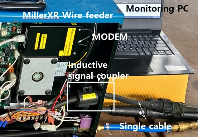
Figure 1 shows a wire feeder (MillerXR model, USA) equipped with communication devices for shipyard-IoT. The device has a built-in modem for Wi-Fi and PLC and an inductive signal coupler for contactless communication. The inductive signal coupler contains a magnetic core that utilizes a single cable as a communication line without physically damaging it.
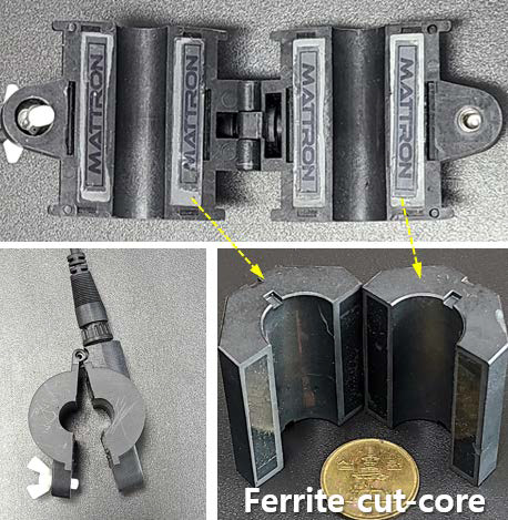
Figure 2 shows the inductive signal coupler developed in this study. Miniaturized Mn-Zn ferrite cores with dimensions of 34×17×44 [mm³] are used for electromagnetic inductive coupling with a single cable. The core is then separated into two pieces. When a non-cut toroid core is used, the magnetic flux is concentrated only inside the core; therefore, there is no magnetic leakage that can induce strong signal coupling. However, the core is easily saturated even at low currents; therefore, it is difficult to apply it to lines with high current fluctuations. Using COMSOL simulations, the magnetic flux density of the ferrite core was visualized to evaluate the efficiency of electromagnetic signal coupling under the influence of the offset current.
2.2 Electromagnetic Properties of the Ferrite Core
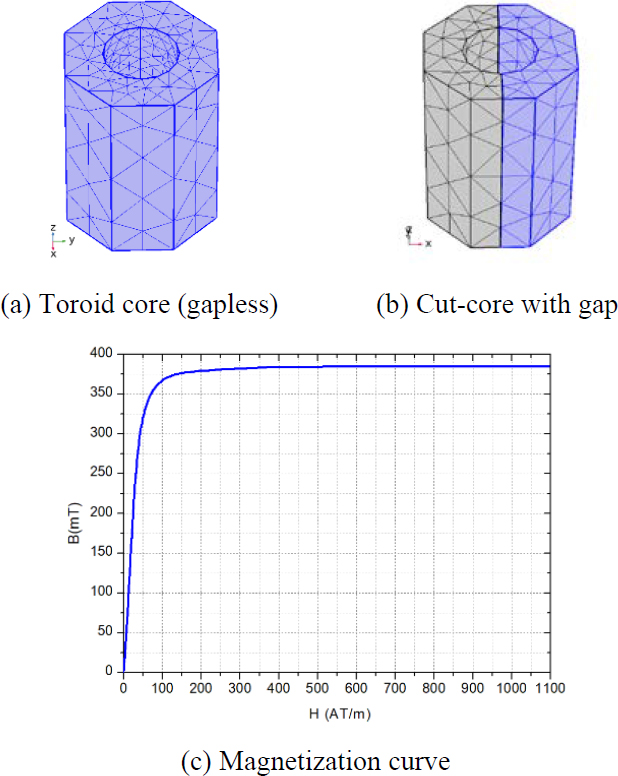
Figure 3 shows the COMSOL 3D mesh model used to visualize the flux distribution in the ferrite core. The simulations were designed to show the flux distributions for the gapless toroidal core (Figure 3(a)) and cut-core with an air gap (Figure 3(b)). The magnetization curve of the core is shown in Figure 3(c), and the maximum saturation flux density was 385 mT (@H = 1170 AT/m). The simulation parameters for evaluating the electromagnetic properties of ferrite as a magnetic core in the coupler are listed in Table 1.
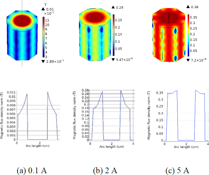
The simulation results for various offset currents are shown in Figure 4. At low line currents (Figure 4(a) and 4(b)), the flux was concentrated at the core center and decreased toward the outer edge. However, when the current reached 5 A (Figure 4(c)), the magnetic flux was evenly distributed across the core at approximately 350 mT, indicating saturation. The saturation of the magnetic core is a major cause of reduced signal coupling efficiency in inductive couplers. Therefore, a method that enables communication even at welding currents exceeding several tens of A is required.
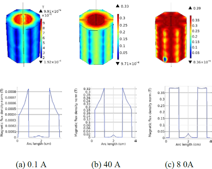
Figure 5 shows the flux density distribution when an air gap of 2 mm was maintained in the cut-core, as shown in Figure 3b. At a line current of 40 A (Figure 5b), the average flux remained at 250 mT within the linear region of the magnetization curve. At 80 A (Figure 5c), the average flux in the inner and outer parts of the core reached 380 mT, approaching saturation.
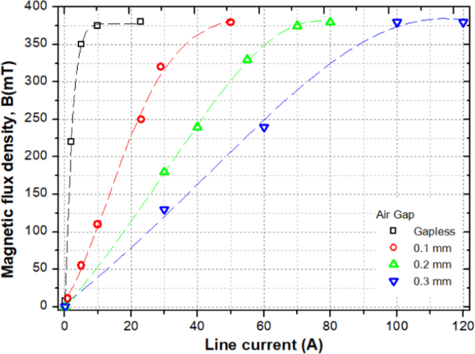
Figure 6 plots the average magnetic flux density of the ferrite core as a function of the air gap and line current. Increasing the air gap lowered the flux density, delaying saturation to higher currents. Proper air gap adjustment is essential to maintain communication bandwidth and provides an effective solution to flux saturation problems caused by peak current fluctuations in single cables.
2.3 Analysis of the Inductive Signal Coupler
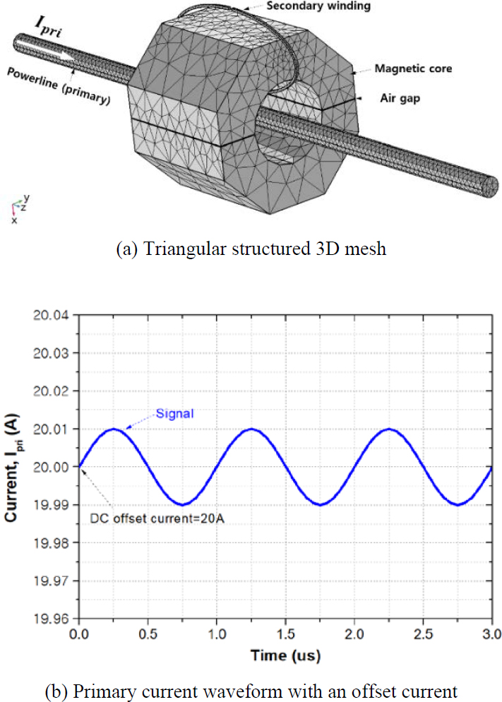
Figure 7a shows a 3D model of the coupler designed for a single cable in a wire feeder. The core consists of a magnetic core and a secondary coil wrapped around it, while the wire serving as the primary coil passes through the center. The primary current is given as Ipri=Ioffset+Iosinωt, where Ioffset represents the DC offset current and Iosinωt is the signal. The welding machine body supplies DC current for welding through a single cable to the wire feed. In the simulation, this was set to DC off current. The performance was determined by the electromotive force induced in the secondary coil by the primary current.
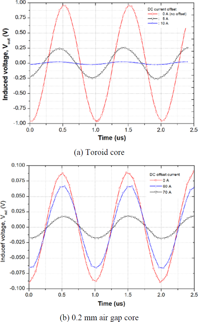
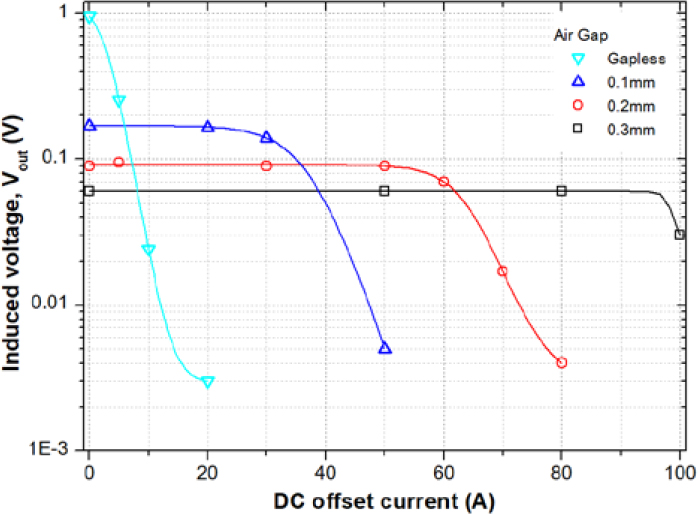
The simulation results for the toroid core signal coupler without an air gap are shown in Figure 8a. When there was no offset current, the peak voltage induced by the 10 mA-1 MHz signal was 1 V. However, at an offset of 5 A, the peak voltage dropped to 0.25 V, and at an offset of 10 A, the core reached saturation. To allow the signal coupler to operate at higher offset currents, the magnetic reluctance of the core must be increased. This is typically achieved by adding an air gap to the magnetic path. Figure 8b shows the waveform of the induced voltage when the air gap was 0.2 mm. Even with an offset current of 60 A, the peak voltage remained at approximately 0.07 V.
Figure 9 shows the induced voltage for various air gaps as a function of the offset current. Providing an adequate air gap in the core allows stable data transmission even in single cables with large current fluctuations. A larger air gap allows the coupler to operate with larger current fluctuations, but also reduces the induced voltage, requiring a trade-off between current fluctuations and air gaps.
3. Bandwidth Measurement and Results
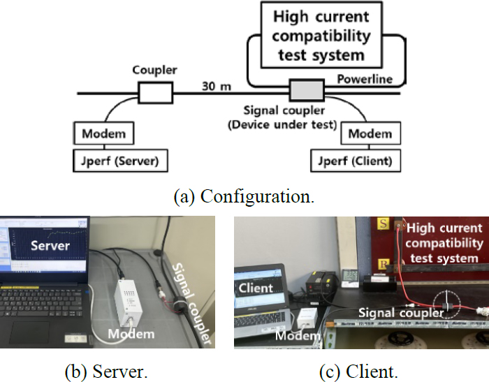
Figure 10 shows the experimental setup used to evaluate the communication performance of the inductive signal coupler. A toroidal signal coupler, which was not affected by the offset current, was installed on the server side to ensure maximum signal coupling. On the client side, a setup was required to measure the effect of the offset current on the data transmission rate. The lead wires of the high-current tester passed through the center of the signal coupler, and the air gap of the ferrite core was maintained at 0.2 mm. This is because the thickness of one sheet of A4 paper is 0.1 mm, therefore inserting this sheet into each cut surface maintained an exact air gap. Communication performance was tested using iperf, a network-testing tool that measures the data throughput between two endpoints in either unidirectional or bidirectional communication.
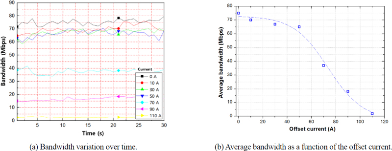
Figure 11 shows the measured bandwidth at various offset currents from 0-110 A. Up to 50 A, the bandwidth remained stable within 10% of the maximum bandwidth. At 70 A, the bandwidth decreased to half of the maximum value, and decreased significantly at 110 A. As shown in Figure 11b, the trend of the average bandwidth according to the offset current was almost identical to that in Figure 9, which shows the simulation results for the induced voltage when the air gap was 0.2 mm.
4. Conclusion
This study has demonstrated, through COMSOL simulations and communication bandwidth measurements, that an inductive signal coupler with an air gap can be effectively utilized with wire feeders and single cables in shipyard-IoT implementation. The toroidal signal coupler cannot guarantee communication linkage owing to the magnetic flux saturation at an offset current of 10 A. However, a signal coupler developed for a single cable can secure a communication bandwidth of > 15 Mbps at 90 A when maintaining a 0.2 mm air gap in the cut-core. In shipyards, where it is difficult to apply fixed communication networks or wireless networks, a wire feeder equipped with the signal coupler developed in this study can realize on-site customized shipyard-IoT.
Acknowledgments
This research was financially supported by the Ministry of SMEs and Startups (MSS), Korea, “Regional Specialized Industry Development Program (R&D, S3365146)” supervised by Korea Institute for Advancement of Technology (KIAT).
Author Contributions
Conceptualization, K. Sohn and H. Kim; Methodology, K. Sohn and H. Kim; Software, K. Sohn; Validation, K. Sohn and H. Kim; Formal Analysis, K. Sohn; Investigation, K. Sohn and H. Kim; Resources, K. Sohn and H. Kim; Data Curation, K. Sohn; Writing—Original Draft Preparation, K. Sohn; Writing—Review & Editing, K. Sohn and H. Kim; Visualization, K. Sohn; Supervision, K. Sohn; Project Administration, K. Sohn and H. Kim; Funding Acquisition, K. Sohn and H. Kim.
References
-
A. A. Zhilenkov, D. D. Gilyazov, I. I. Matveev, and Y. V. Krishtal, “Power line communication in IoT-systems,” 2017 IEEE Conference of Russian Young Researchers in Electrical and Electronic Engineering (EIConRus), Russia, pp. 242-245, 2017.
[https://doi.org/10.1109/EIConRus.2017.7910538]

-
S. U. Ercan, “Power line communication: Revolutionizing data transfer over electrical distribution networks,” Engineering Science and Technology, an International Journal, vol. 52, 101680, 2024.
[https://doi.org/10.1016/j.jestch.2024.101680]

-
H. S. Kim, S. H. Park, and S. G. Kang, “Development of communication joint tools for implementing a legacy-line communication system in a train,” Journal of Korean Institute of Communications and Information Sciences, vol. 19, no. 4, pp. 877-887, 2015.
[https://doi.org/10.6109/jkiice.2015.19.4.877]

-
S. H. Yang, J. H. Jeong, and K. R. Sohn, “Inductive powerline communication performance comparison using nano-crystalline alloy and ferrite coupling device in ship,” Journal of Korean Institute of Communications and Information Sciences, vol. 43, no. 4, pp. 740-746, 2018.
[https://doi.org/10.7840/kics.2018.43.4.740]

-
K. R. Sohn, S. H. Yang, and J. H. Jeong, “Inductive coupling characteristics of nano-crystalline alloy for electric vehicle PLC,” 2018 Tenth International Conference on Ubiquitous and Future Networks (ICUFN), pp. 543-545, 2018.
[https://doi.org/10.1109/ICUFN.2018.8436996]

-
M. E. M. Ussdek, S. A. M. Al Junid, Z. A. Majid, F. l N. Osman, and Z. Othman, “High-sensitivity gas detection and monitoring system for high-risk welding activity,” 2013 IEEE Conference on Systems, Process & Control (ICSPC), pp. 256-261, Malaysia, 2013.
[https://doi.org/10.1109/SPC.2013.6735143]

- Y. D. Seung and J. B. Tae, “IoT based safety management system in closed space,” Proceeding of the 2016 Summer Conference of KICS (Korea Information and Communications Society), pp. 1114-1115, Korea, 2016.
- T. H. Yoon, W. S. Jung, D. S. Yoo, and H. K. Choi, “LoRaWAN class yard: Development of LoRaWAN relay system to overcome radio shadow area,” Korea Information and Communications Society summer conference, pp. 724-725, Korea, 2018.
-
K. R. Sohn and H. S. Kim, “Inductive coupling characteristics of air-core toroid coil and its application in power line communication,” Journal of Advanced Marine Engineering and Technology, vol. 45, no. 1, pp. 26-30, 2021.
[https://doi.org/10.5916/jamet.2021.45.1.26]

-
K. R. Sohn and H. S. Kim, “Magnetic induction communication using toroidal helix coil,” Journal of Advanced Marine Engineering and Technology, vol. 46, no. 3, pp. 122-127, 2022.
[https://doi.org/10.5916/jamet.2022.46.3.122]

-
K. R. Sohn and H. S. Kim, “Overcoming radio shadow areas in confined spaces using an IoT-based wire-feeder and power-line communication and its application to shipyard safety monitoring systems,” Journal of Advanced Marine Engineering and Technology, vol. 47, no. 6, pp. 379-384, 2023.
[https://doi.org/10.5916/jamet.2023.47.6.379]


