A study on emission reduction characteristics of a transfer crane engine

Copyright © The Korean Society of Marine Engineering
This is an Open Access article distributed under the terms of the Creative Commons Attribution Non-Commercial License (http://creativecommons.org/licenses/by-nc/3.0), which permits unrestricted non-commercial use, distribution, and reproduction in any medium, provided the original work is properly cited.
Abstract
In 2020, the Ministry of Oceans and Fisheries introduced the Special Law for Air Quality Improvement in Port Areas to replace outdated cargo-handling equipment with eco-friendly alternatives. This study focuses on reducing emissions from a transfer crane engine at Shin Gamman Port in Busan by implementing aftertreatment devices. In this regard, an aftertreatment device was developed and installed on a 500 kW-class engine testbed for performance evaluation. The device comprises catalysts designed to reduce unburned hydrocarbons (THC), carbon monoxide (CO), nitrogen oxides (NOx), and particulate matter (PM), as well as an additional catalyst to remove ammonia (NH3) generated during the NOx reduction process. After installation, the device achieved over 80% reduction in NOx and PM and more than 90% reduction in THC and CO, demonstrating its effectiveness for controlling emissions. This paper presents the methods, results, and future improvements for optimizing urea injection control and broadening its applicability to other equipment. The findings provide insights into the adoption of environmentally friendly technologies such as aftertreatment devices in industrial machinery.
Keywords:
Diesel engine, Selective catalytic reduction (SCR), Nitrogen oxide (NOx), Particulate matter (PM), Urea, Ammonia (NH3), Transfer crane (T/C)1. Introduction
This study addresses a critical environmental issue arising from diesel engine emissions from port facilities. As ports are hubs of economic activity, achieving sustainability requires a balance between operational efficiency and environmental stewardship. Previous studies have shown the significant health and ecological impacts of nitrogen oxides (NOx) and particulate matter (PM), particularly in densely populated urban areas adjacent to ports [6]. This study contributes to the broader discourse on green technology adaptation in heavy-duty equipment.
Owing to their high torque and low fuel consumption, diesel engines have significantly contributed to the development of human industry. They are particularly essential as primary power sources in port facilities, where lifting heavy loads and moving cargo are vital. However, the compression-ignition combustion in diesel engines, characterized by high combustion temperatures and diffusion flames in the combustion chamber, produces significant amounts of nitrogen oxides (NOx) and PM. These emissions contribute to air pollution, including photochemical smog and fine PM, which have been proven to accumulate in the human body over time and have severe health impacts.
In response, the government enacted the Special Act on the Reduction and Management of Fine Dust in 2019, followed by the Green Ship Act and the Special Act for Air Quality Improvement in Port Areas in 2020, aimed at reducing harmful emissions in port areas. To continue the use of diesel engines, which are prevalent in port cargo-handling equipment, research on reducing the harmful emissions from these engines is essential.
Among the existing efforts to reduce NOx and PM emissions from diesel engines, further research is needed on exhaust after-treatment technologies such as Selective Catalytic Reduction (SCR) and Diesel Particulate Filter (DPF) systems. SCR technology reduces NOx by injecting urea as a reductant and converting NOx into nitrogen and oxygen. However, excessive urea injection can lead to unreacted urea, resulting in ammonia slipping, where toxic ammonia (NH3) is released into the atmosphere. According to [1], studies applying SCR to ships have reduced NOx emissions and proposed designs to address ammonia slip.
In this study, a Hyundai D6CB engine installed on an engine testbed was selected as the test engine. An aftertreatment device was installed at the rear of the engine to reduce harmful emissions. The device was subsequently installed on a transfer crane at Busan's Shin Gamman Port, where NOx and PM emissions were analyzed under real-world operating conditions. The after-treatment device consisted of a Diesel Oxidation Catalyst (DOC) to reduce unburned hydrocarbons (THC), carbon monoxide (CO), PM, and NOx, and an Ammonia Oxidation Catalyst (AOC) to eliminate ammonia (NH3). The system was designed in 3D and installed at the rear end of the transfer crane after modification to ensure proper fitting.
2. Engine Specifications and Test Method
2.1 Engine Specifications and Test Setup
Tables 1 and 2 present the specifications of the Hyundai D6CB and Cummins KTA19-G3 engines used in this study. The Hyundai D6CB engine is a water-cooled, inline, six-cylinder diesel engine with a turbocharger for forced air induction. The engine has a displacement of 12.4 L, a maximum power output of 410 horsepower (HP), and a maximum torque of 800 Nm. The KTA19-G3 engine has the same cylinder and turbocharging structure as the D6CB. However, the enging features a larger displacement of 19 L and a maximum output of 685 HP.
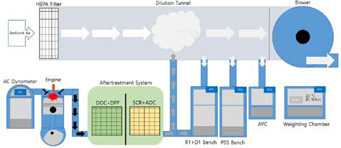
Figure 1 shows the configuration of the equipment used to measure the exhaust emissions from the Hyundai D6CB engine installed on an engine testbed. The exhaust gases were released from the rear of the engine, mounted on a 500 kW dynamometer (AC Dynamometer, AVL, Austria), and diluted with ambient air filtered through a Hepa filter in a dilution tunnel (CVS, AVL, Austria). The diluted exhaust gases were collected in a dilution bag on an analysis bench (R1+D1 bench, AVL, Austria), and the concentrations of the exhaust components were measured using the bag analysis method. Additionally, an undiluted exhaust sampling port was installed directly after the reduction device to analyze the exhaust components without dilution. The analysis bench could measure THC, CO, NOx, and CO2. PM was collected using a PSS i60 (Particle Smart Sampler, AVL, Austria) and weighed in a temperature and humidity-controlled chamber (weighing chamber, AVL, Austria). Particulate number (PN) was measured using an APC device (APC, AVL, Austria), which sprayed 99% pure butanol and employed an optical transmittance measurement method to determine PN concentration.
Table 3 lists the specifications of the analysis modules on the analysis bench (R1+D1 bench, AVL, Austria). THC were measured using the Flame Ionization Detector (FID) method. CO and CO₂ were measured using the non-Dispersive Infrared Detector (IRD) method. NOx was measured using the Chemiluminescence Detector (CLD) method.
2.2 Test Method
The KC1-8 Mode Measurement Method, which simulates varying operational conditions, was selected owing to its robustness in capturing the transient and steady-state emission data. This method comprises eight segments with precise control over the speed and torque to replicate real-world engine load profiles. A high-precision AVL dynamometer and state-of-the-art gas-analysis modules were employed to ensure data accuracy. Calibration routines were conducted before each test session to minimize measurement deviations.
The test was conducted according to the specifications listed in Table 4, based on the Automobile Testing and Inspection Regulations under KSR 0071, A conditions. During engine operation, the emissions of THC, CO, NOx, and PM were calculated in grams per kilowatt-hour (g/kWh) using the Puma Gem301EC software (AVL, Austria) for automated data processing. The intake air temperature was set to 25 °C with 40 %R.H., and the PM filter was conditioned for over 4 h at 22 °C and a 9.5 °C dew point before the test to measure its base weight. After testing, the filter was reconditioned for 2 h, and the weight was measured again. The reduction rate was evaluated by comparing engine emissions with and without the aftertreatment device.
3. Test Results
3.1 Engine Lab Test Results
The analysis revealed that the NOx reduction was highly dependent on the catalyst activation temperature, as indicated by the reduced efficiency under low-load and idle conditions. This observation aligns with the existing literature results, which underscore the thermal dependence of SCR systems. Interestingly, the NH3 emissions peaked under specific modes, suggesting an imbalance in urea injection calibration under fluctuating load scenarios. These findings highlight the importance of dynamic control strategies for optimizing emission reduction across diverse operating modes.
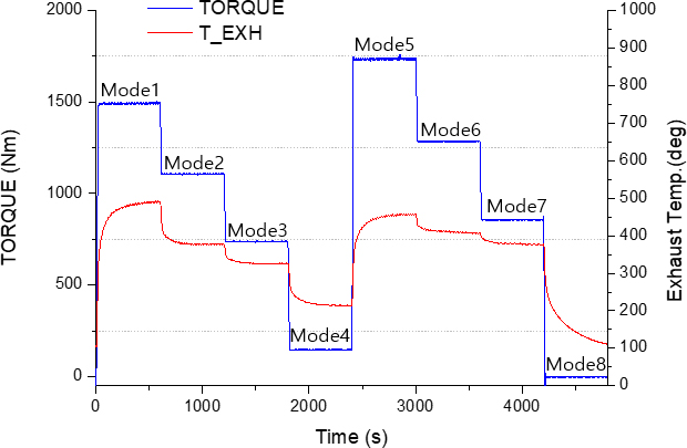
Figure 2 shows the load and temperature conditions for the KC1-8 mode. The catalysts in the post-treatment device achieved an optimal reduction rate at temperatures above 300 °C [1]. Thus, excluding the low-load conditions in Mode 4 and idle conditions in Mode 8, the optimal temperature conditions were satisfied.
To prevent ammonia slip, urea injection was minimized in Modes 4 and 8, where the temperature was below the catalyst activation threshold.
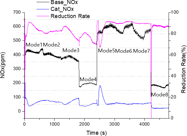
Figure 3 compares the NOx emissions of the engine before and after installing the aftertreatment device, showing the reduction rate. Base_Nox refers to the engine test conditions without an aftertreatment device, whereas Cat_Nox represents the engine test conditions with an aftertreatment device. At 1900 rpm, emissions were approximately 400 ppm, with over 80% reduction rate achieved in all modes except Mode 4 and the beginning of Mode 5, where the load rapidly increased. In Mode 4, the exhaust temperature was below the catalyst activation temperature of 300 °C, limiting aggressive urea injection and leading to a lower reduction rate. The initial phase of Mode 5 experienced a drop in the reduction rate owing to the rapid load changes, to which the urea injection system could not dynamically adjust.
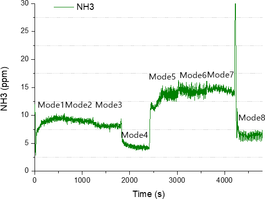
Figure 4 shows the real-time NH3 emissions during operation. Urea injection involves endothermic and hydrolytic reactions that release ammonia and reduce NOx to nitrogen and water. However, when the exhaust temperature is below the catalyst activation temperature of 300 °C, ammonia is ineffective for NOx reduction and is instead emitted as ammonia slip. The graph shows that ammonia emissions remained below 10 ppm in the first four modes, increased to approximately 15 ppm in Mode 5, and peaked at 30 ppm in Mode 8. This peak in Mode 8 resulted from the accumulation of unreacted urea from the high NOx reduction activity in Modes 5–7, which was later emitted as ammonia. Improvements in AOC are required to reduce ammonia emissions further.
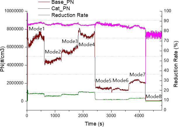
Figure 5 shows the real-time PN concentrations of PM. The combustion of diesel in diffusion flames generates solid carbon nuclei, which aggregate to form soot particles. The graph shows that the PN emissions were higher in high-speed modes 1, 2, 3, and 4 and significantly lower in low-speed modes 5, 6, 7, and 8. The reduction rate exceeded 80% in all modes, except for the idle condition in Mode 8.
Table 5 presents a comparison of the exhaust gas reduction efficiencies before and after installing the aftertreatment device. NOx and PM showed a reduction rate of over 80%, whereas THC and CO achieved a reduction rate of over 90% due to the DOC catalyst.
3.2 Field Test Results on Transfer Crane
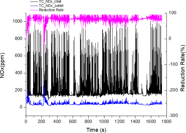
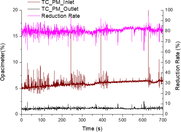
Figures 6 and 7 show the NOx and PM emissions from the transfer crane equipped with the aftertreatment device. The measurements were obtained over approximately three hours under transient conditions that did not interfere with operational tasks. Analysis of the NOx and PM emission trends confirmed that the device satisfied its reduction rate target of over 80%, although certain sections exhibited reduced efficiency owing to the less responsive urea injection. Future improvements to the control logic are necessary to address this issue.
Transient conditions are defined as the variable operational states experienced during regular crane activities, including load changes and idle periods. The graphs below highlight data trends under these conditions.
Although the aftertreatment device demonstrated significant emission reduction in the tested transfer crane, its performance may vary in other types of port equipment and operational environments. Future studies should explore the scalability and adaptability of this technology to a broader range of heavy-duty machinery to ensure its effectiveness in diverse scenarios. This includes considering variations in engine specifications, operational loads, and environmental conditions.
4. Conclusion
This study aimed to improve air quality in port areas by installing an aftertreatment device on a transfer crane in accordance with the Special Act for Air Quality Improvement in Port Areas. The initial design of the device was based on emission data from a transfer crane, and its performance was evaluated through KC1-8 mode operation on an engine testbed. The results showed that NOx and PM emissions were reduced by over 80%. The device was applied to actual port equipment to reduce emissions under real-world conditions. Although the urea injection responsiveness was inadequate in some segments, suggesting the need for control logic optimization, the device successfully reduced the overall emissions.
Future research should explore adaptive control algorithms that leverage machine learning to adjust urea injection rates dynamically based on real-time engine telemetry. In addition, scaling up the system for application to larger marine engines and integrating renewable energy sources for auxiliary power could significantly enhance the sustainability of port operations.
Acknowledgments
This study was supported by the project Development and Demonstration of Exhaust After-Treatment Systems for Transfer Cranes in Busan Port, with additional support from Busan Port Authority and Hyundai Materials, to whom we extend our gratitude.
Author Contributions
Conceptualization, G. B. Cho; Methodology, G. B. Cho and K. B. Son; Software, S. W. Lee; Formal Analysis, U. H. Lee; Investigation, N. K. Kim and K. B. Son; Resources, Y. W. Kim; Data Curation M. J. Kim; Writing-Original Draft Preparation, M. J. Kim; Writing-Review & Editing, S. W. Lee; Visualization, I. H. Kim; Supervision, G. B. Cho; Project Administration, S. H. Kim.
References
-
Y. H. Ryu, H.R. Kim, G. B. Cho, H. S. Kim, and J. G. Nam, “A study on the installation of SCR system for generator diesel engine of existing ship,” Journal of the Korean Society of Marine Engineering, vol. 39, no. 4, pp. 412-217, 2015.
[https://doi.org/10.5916/jkosme.2015.39.4.412]

-
Y. H. Ryu, Y. S. Lee, and J. G. Nam, “An experimental study of the fuel additive to improve the performance of a 2-stroke large diesel engine,” Journal of the Korean Society of Marine Engineering, vol. 39, no. 6, pp. 620-625, 2015.
[https://doi.org/10.5916/jkosme.2015.39.6.620]

-
Y. H. Ryu, Y. S. Lee, and J. G. Nam, “Performance and emission characteristics of additives-enhanced heavy fuel oil in large two-stroke marine diesel engine,” Fuel, vol. 182, pp. 850-856, 2016.
[https://doi.org/10.1016/j.fuel.2016.06.029]

-
Y. H. Ryu, T. W. Kim, J. S. Kim, and J. G. Nam, “Experimental study of NOx reduction in marine diesel engines by using wet-type exhaust gas cleaning system,” Journal of the Korean Society of Marine Engineering, vol. 41, no. 3, pp. 216-221, 2017.
[https://doi.org/10.5916/jkosme.2017.41.3.216]

- N. W. Jo, S J. Moon, Y. R Lee, and G W. An, “Research on the flow characteristics according to the catalyst layout in heavy-duty diesel engine,” The Korean Society of Automotive Engineers, pp. 281-284, 2015.
-
H. M. Lee and R. E. Park, “Exhaust emission characteristics from heavy-duty diesel engine applicable to prime propulsion engine for marine vessels,” Journal of the Korean Society of Marine Engineering, vol. 36, no. 4, pp. 484-489, 2012.
[https://doi.org/10.5916/jkosme.2012.36.4.484]

- J. B. Heywood, Internal Combustion Engine Fundamentals, New York, USA: McGraw-Hill, Inc., 1988.
-
D. K. Ko, S. Y. Jeong, I. S. Kim, G. W. An, and Y. W. Nam, “Study on the on-board test of after-treatment systems to reduce PM-NOx in low-speed marine diesel engine,” Journal of the Korean Society of Marine Environment & Safety, vol. 29, no. 5, pp. 497-504, 2023.
[https://doi.org/10.7837/kosomes.2023.29.5.497]

-
Y. S. An, H. S. Lee, and J. W. Lee, “Analysis of carbon emission reduction effect due to electricity conversion of container port’s CHE,” Journal of Korea Port Economic Association, vol. 40, no. 2, pp. 49-52, 2024.
[https://doi.org/10.38121/kpea.2024.6.40.2.39]

- S. C. Jung and W. S. Yoon. “Unified modeling and performance prediction of diesel NOx and PM reduction by DOC-DPF-SCR system,” Transactions of the Korean Society of Automotive Engineers, vol. 16, no. 4, pp. 110-119, 2008.

