Evaluation of natural frequency and critical speed of the rotating structure using ANSYS
Copyright © The Korean Society of Marine Engineering
This is an Open Access article distributed under the terms of the Creative Commons Attribution Non-Commercial License (http://creativecommons.org/licenses/by-nc/3.0), which permits unrestricted non-commercial use, distribution, and reproduction in any medium, provided the original work is properly cited.
Abstract
This study aims to support stable and efficient system operation by analyzing the dynamic characteristics of the Rotation Packed Bed (RPB) system. The RPB system provides high mass transfer performance due to high-speed rotation, but it is affected by natural frequencies and critical speeds and has an important effect on the stability of the system. In this study, through ANSYS modal analysis, to evaluate vibration characteristics according to the rotational speed of RPB system, natural frequency and mode deformation of RPB system modelling are analyzed, and the frequency change according to the rotational speed is shown using the Campbell diagram. As a result, the critical speeds at 13,184 rpm and 16,658 rpm are confirmed at the given condition based on RPB modelling, and it is recommended to maintain operating (rotation) speed of 9,228 rpm (with considering a separation margin of about 20%) or less for stable. This study can provide design guidelines for strengthening dynamic stability in high-speed rotating systems like RPB system.
Keywords:
Rotordynamic, Natural frequency, Critical speed, ANSYS modal, Campbell diagram, Finite element analysis1. Introduction
The CCS (Carbon Capture Storage) is attracting attention as an important way to reduce greenhouse gas emissions. In particular, RPB (Rotation Packed Bed) effectively captures carbon generated from the use of fossil fuels and industrial activity to prevent it from being released into the atmosphere. RPB systems which are widely used for efficient reaction and separation in industrial processes, are characterized by improving mass transfer performance through high rotational speed. RPB can be applied to various processes such as chemical reaction, gas-liquid separation, and gas absorption, which can provide better reactivity and efficiency than traditional filling towers. Unlike conventional turbine and centrifuges, the RPB system must meet certain operational requirements that must consider high speed mass transfer efficiency, which requires additional condition or optimization that may not be a priority for other system. However, since RPB operates based on high-speed rotation, dynamic characteristics such as intrinsic frequency have an important influence on the performance and stability of the system, Improper design and operation can lead to mechanical damage or performance degradation. The natural frequency refers to the possibility of system resonance at a particular frequency, and when this frequency is connected, the vibration can be amplified, which can lead to structural damage or instability. In particular, it is essential to identify the risk of such resonances in advance in high-speed rotating systems such as RPB and to determine the safe operating speed through risk speed analysis. Analysis and simulation of the natural frequency and risk speed is an important factor in the design and operation of the RPB system, which prevents accidents and enables stable and efficient process operation. For this reason, many researchers are conducting research on the rotordynamics. For many years, the Ansys dynamic programs are usually used for rotordynamics as new analytical requirements, the quality of analytical methods, computer function increase [1]. Bae et al. calculated the actual number of revolutions applied to the gear of the mixer reducer considering the working mode of the 6-8m³ concrete mixer truck, applied the proposed specifications to calculate the natural frequency, and analyzed it using Campbell's diagram [2]. Kwon et al. compared and analyzed the calculated transient vibration response using the RK4 rotor kit’s vibration and ANSYS MAPDL [3]. Son et al. tried to design to avoid resonance by changing design parameter such as diameter and length of the shaft [4]. Jo et al. performed a vibration measurement experiment of laundry using an acceleration sensor to verify the accuracy of the FEM (Finite Element Model) and compared it with the result of FEM, and reduced vibration by getting the results when the elastic mount was installed to improve the design [5]. Afane, N.E.B. et al. performed modal analysis by applying various materials to the rotating body model and compared the results. As a result, it is confirmed that the modes in the high frequency area is large according to the order of the Young’s modulus. However, the change in the low frequency area is small. So it doesn’t significantly affect the critical speed. In addition, harmonic analysis was conducted to analyze the results by adding an unbalanced mass condition to the rotating body model [6]. Saxena, A et al. was shown that the bearing stiffness can have a significant impact on the dynamics of the geared system [7]. Jung et al mentioned that critical speed that is a typical dynamic characteristic of a rotating body is a happening that the rotational speed of the system coincides with the natural frequency and causes resonance. It directly affects the structural stability of the system and damage. [8] ZAHAF et al. used FEM to improve the stability of the structure, make an optimal design method, or analyze the effect of parameter on the performance of the structure [9]-[18]. So far, there is no research results reported related dynamic characteristics of RPB system especially related to packing. Thus, in this paper, Ansys Modal analysis is performed to understand the vibration characteristics caused by the rotational motion of packing of the RPB and to evaluate the structural stability accordingly. Through this, the natural frequency and vibration mode of the RPB according to packing and suggest a way to solve the vibration problem related to rotational motion, such as preventing resonance by matching the natural frequency of the modeling and the rotational frequency using the Campbell diagram can be analyzed.
2. Finite Element Modeling of Rotating Structure
2.1 Modeling and Property
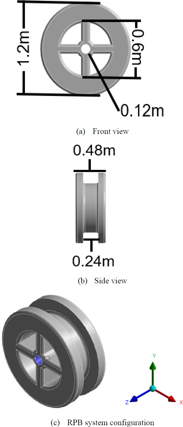
The modeling of rotation structure is designed directly with the concept diagram of packing used in RPB system. Modeling configuration is presented at Figure 1. Outer diameter is 1.2 m and the diameter of the inner diameter hole is 0.12 m. Total thickness is 0.48 m. Inner diameter is 0.24 m. Furthermore, the added rib structure has a cross-shaped added rib inside, which adds structural stability. Since the shaft is inserted in the axial direction of the z-axis, the coordinate system was set like (c) in Figure 1. Material properties are shown in Table 1. The damping ratio is defined to 0.002%.[19]
2.2 Meshing and Accuracy Verification
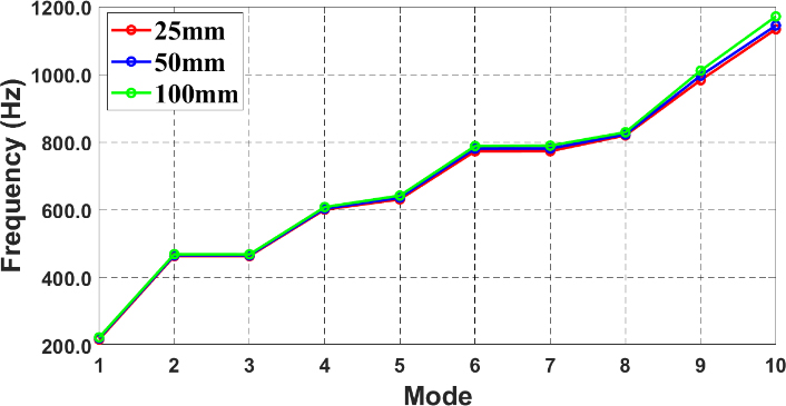
Mesh size and quality are important factors to increase the accuracy of the analysis results, and more detailed vibration modes and natural frequencies can be captured, especially with small meshes. Therefore, it is necessary to secure the reliability of the analysis results through the mesh checking procedure. So, this paper observed the change in natural frequency when the mesh size of 25mm, 50mm, 100mm is used for modal analysis. All case of Meshes is set to the tetrahedral method. Figure 2 is shown mesh of modeling. The total node generates 53589,15507,6934 respectively. Table 2 and Figure 3 presents the results of different mesh sizes under the same conditions and comparing the results. As shown as Figure 3, the 3 cases seem to match each other very well and the accuracy of mesh convergence can be proved. In this analysis, a size of 25mm is applied for the most accurate result.
3.Modal Analysis
3.1 Conditions
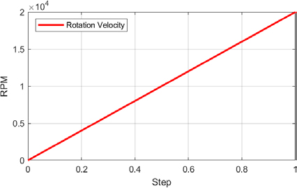
All of 6 DOF (degree of freedom) except for the rotational z are fixed (it means that only rotation about z-axis is allowed). In this study, it is also assumed that the rotational motion will be performed based on the z-axis to consider the effects of the gas, water pipe which is needed material essential for carbon capture. So, the cylinder support condition is applied to the hole where the pipe and shaft would enter. The hole is marked in blue (c) in Figure 1. This analysis is conducted under the condition of the RPB system at temperature of 22℃ in vacuum. The rotational velocity increases linearly 0 to 20,000 rpm, as shown in the Figure 4. It can be considered that the rotational velocity affects modal analysis as an external force. In the modal analysis performed by ANSYS, the rotation velocity is defined as boundary conditions, not factors acting as external forces. Because they are modeled as additional conditions that affect the dynamic response of the system to reflect the gyroscopic effects caused by rotation. In general, the 2nd order differential equation of dynamic system takes the form of Equation (1). However, when the rotational velocity is applied to fundamental equation, there is change in the dynamic response of the system. In particular, the gyroscopic matrix is added to the equation of motion.
| (1) |
● M : Mass Matrix
● C : Damping Matrix
● K : Stiffness Matrix
● u(t) : displacements vector
● : velocity vector
● : acceleration vector
● F(t) : external force vector
In rotordynamics, the gyroscopic effect and the rotating damping effect are additionally included, expressed by Equation (2). The gyroscopic effect induces a velocity-dependent force, which is included into the 2nd order equation of dynamic system in a way similar to the system. Also, it describes the additional dynamic effects that arise with the speed of rotation when a rotating structure vibrates. This matrix is generally asymmetric, increasing the complexity of the vibration modes in rotating body systems [20]. For example, it adds complex number components to natural frequencies, allowing the natural vibration mode to take on a complex mode form rather than a simple sinusoidal mode. Therefore, in the modal analysis of the rotation body, the 2nd order equation of dynamic system is modified as follows:
| (2) |
● G(Ω) : Gyroscopic Matrix
● B(Ω) : Rotating Damping Matrix
● Ω : Rotational velocity
The gyroscopic matrix G(Ω) is related to rotational speed and must be considered when analyze rotordynamics. Furthermore, rotating damping matrix B is dependent on the speed of rotation, changing the stiffness of the structure and causing unstable motion. ANSYS modal analysis performs the process of calculating a linear equation that doesn’t consider additional external force as a basic premise.
3.2 Natural Frequency
The values of natural frequencies show the vibration characters of the system, indicating the possibility that the system will be resonance at certain frequencies. Table 3 presents the modes at 0 rpm and 20,000 rpm. The mode is obtained to 10 mode. At natural frequency of 20,000 rpm, the mode 1 remain at the same value as at 0 rpm. This is one of the vibration characteristics of the system which is not affected by rotational velocity. The other modes are slightly changing due to the initial force of gyroscopic, colioli effects of rotation.
3.3 Mode Shape
The mode shape refers to the deformation shape when the system vibrates at a specific natural frequency. It is important for understanding the vibration characteristic of the system and can identify structural weaknesses. Figure 5 is shown the 10 modes shape at 20,000 rpm. As shown in Figure 5, the specified 10 modes showed unique patterns, including bending and twisting effects, respectively. Mode 2, 3 are observed that the torsion mode has occurred. Since mode 1 is a low frequency area, there is no noticeable deformation. In the mode 4, a bending mode occurred in the z-axis direction. In high modes, the bending and torsion effects appear in combination, due to the influence of gyroscopic and corioli effects in high-speed rotation. High frequency modes generally have a greater impact on the stability and durability of the structure.
3.4 Campbell Diagram and Critical Speed
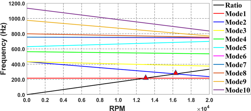
Campbell diagram is used to present rotor dynamic results in this study. It accurately identifies resonance points at specific rotation velocity and compares them to range of rotation velocity to establish safe operating conditions.[21] Figure 6 is shown the Campbell diagram results (relationship between RPM and modes). In the Figure 6, x-axis label is RPM and the y-axis label is frequency. A black line (“RATIO”) means the rotation velocity. It means that if this is in contact with the line that defined as the mode, resonance will occur. As shown in Figure 6, the lower modes are not change even when the rotation velocity increases. This is because the gyroscope effect acts relatively small then the higher modes. In the higher modes, mode separation in which the frequency changes as the rotation velocity increasing is observed. This is a representative feature of the gyroscopic effect [22]. In this graph, it can be observed that critical speeds are defined 13,184 rpm and 16,658 rpm since the black line (“RATIO”) is contacted with mode 1 at 13,184 rpm and mode 2 at 16,658 rpm.
4. Conclusion
In this study, the dynamic characteristic of packing used in RPB system are analyzed using the ANSYS modal analysis. Also, Campbell diagram is plotted to verify natural frequencies and critical speeds with 0 to 20,000 rpm range at given boundary condition. It is assumed that during operating stage, the rotating structure (= packing of RPB system) spins, and natural frequencies (mode) vary at each rpm, and resonance may occur if it matches the applied rpm based on Campbell diagram. After that, the following results and conclusion are obtained:
- (1) In the analysis, it is confirmed that the critical speed are 13,184 rpm,16,658 rpm because it is contacted with mode 1 at 13,184 rpm and mode 2 at 16,658 rpm.
- (2) If the amplification factor doesn’t consider in the rotation system, a separation margin of about 20% or more is usually required between the operating speed or the specific rotation speed and the critical speed [23]. In this conclusion, the separation margin is set to 30%, and the rotational speed is recommended to under 9228rpm.
- (3) Additionally, RPBs used in general real industries are recommended to operate at much lower rpm than 20000 rpm [24]. For conservative design, this paper applied an operating speed up to 20000 rpm. Therefore, it can be seen that when real models are introduced into the industry, they are less likely to resonate from critical speeds.
Limitation and Future Work
This study performed a vibration analysis on the packing of the CCS device RPB, but the scope of the analysis is limited since external load and temperature and pressure, is not considered. This is because the basic condition of the ANSYS modal analysis focuses on analyzing the vibration characteristics of the structure without external force. Therefore, an additional analysis is needed considering the effects of external thermal and pressure on the dynamic response of RPB.
In addition, in order to realize this possibility in practice, it is necessary to closely invest practical problems such as cost and scalability. Accordingly, future works will conduct a technologies demand survey and conduct substantiation based on this to evaluate the commercial applicability under actual operating conditions.
Furthermore, since it is analyzed under the assumption that the stiffness of the bearing is very high, it is processed by converging the stiffness to infinity. Therefore, the future study will be conducted how the results change as the bearing characteristic changes.
Moreover, this study analyzes only one model and one material, even though the natural frequency and critical speed can vary greatly depending on the modeling size and material of the model. Therefore, we will conduct further studies to compare the results according to the modeling and materials including structure mechanical characteristics
Also, in this study, the actual RPB system is not completely implemented, but a random model is produced by referring to the actual model. Through future research, a study will be conducted to compare the acceleration result of the actual RPB with the result value of the interpretation.
Acknowledgments
This paper was conducted with the support of the Korea Institute of Industrial Technology and Promotion with the financial resources of the government (Ministry of Trade, Industry and Energy) in 2024. (RS-2024-00424595, project to train high-quality researchers for the next generation of marine mobility industry innovation).
Author Contributions
Conceptualization, Y. J. Lee, W. C. Chung and S. G. Cheon; Methodology, Y. J. Lee and W. C. Chung; Software, Y. J. Lee; Formal Analysis, Y. J. Lee; Investigation, Y. J. Lee and W. C. Chung; Resources, Y. J. Lee, W. C. Chung and S. G. Cheon; Data Curation Y. J. Lee and W. C. Chung; Writing-Original Draft Preparation, Y. J. Lee and W. C. Chung; Writing-Review & Editing, Y. J. Lee and W. C. Chung; Visualization, Y. J. Lee; Supervision, W. C. Chung; Project Administration, W. C. Chung and S. G. Cheon; Funding Acquisition, W. C. Chung and S. G. Cheon.
References
-
M. S. Kumar, “Rotor dynamic analysis using ANSYS,” In IUTAM Symposium on Emerging Trends in Rotor Dynamics: Proceedings of the IUTAM Symposium on Emerging Trends in Rotor Dynamics, held in New Delhi, India, pp. 153-162, Springer Netherlands, 2011.
[https://doi.org/10.1007/978-94-007-0020-8_14]

- M. H. Bae, T. Y. Bae, and D. J. Kim, “The critical speed analysis of the differential planetary gear train of a concrete mixer truck mixer reducer,” Journal of Drive and Control, vol. 14, no. 1, pp. 1-7, 2017.
-
K. B. Kwon, J. H. Jung, and S. H. Han, “Abnormal condition analysis and validation of RK4 multi axis rotor systems using finite element analysis,” Transactions of the Korean Society for Noise and Vibration Engineering, vol. 28, no. 2, pp. 204-213, 2018.
[https://doi.org/10.5050/KSNVE.2018.28.2.204]

-
C. Y. Son, K. S. Lee, and Y. H. Ryu, “A study on the vibration characteristics of critical speed for rotor shaft,” Transactions of the Korean Society for Noise and Vibration Engineering, vol. 18, no. 9, pp. 961-971, 2008.
[https://doi.org/10.5050/KSNVN.2008.18.9.961]

- Y. J. Jo, Y. J. Han, Y. J. Cho, and G. H. Jang, “Axial vibration reduction of a wall-mounted drum-type washing machine,” Spring and Autumn Conference of the Korean Society of Mechanics, pp. 2125-2130, 2018.
- N. E. B. Afane, S. Zahaf, M. Dahmane, A. Belaziz, and R. Noureddine, “Modal and harmonic analysis of the rotor system involving four different materials by finite element code: Ansys workbench,” Materials Physics and Mechanics, vol. 51, no. 7, pp. 63-98, 2023.
-
A. Saxena, A. Parey, and M. Chouksey, “Study of modal characteristics of a geared rotor system,” Procedia technology, vol. 23, pp. 225-231, 2016.
[https://doi.org/10.1016/j.protcy.2016.03.021]

- S. H. Jung, K. S. Choi, and J. Y. Kim, “Study of the parameters effecting on the critical speed of a rotor system,” The Korean Society for Aeronautical and Space Sciences, 2011.
- S. ZAHAF, M. DAHMANE, A. BELAZIZ, et al., “Failure analysis of semi-elliptical crack behavior in the cement mantle of a total hip prosthesis,” Materials Physics & Mechanics, vol. 48, no 2, 2022.
-
A. MESTAR, S. ZAHAF, N. ZINA, et al., “Development and validation of a numerical model for the mechanical behavior of knee prosthesis analyzed by the finite elements method,” Journal of Biomimetics, Biomaterials and Biomedical Engineering, vol. 37, p. 12-42, 2018.
[https://doi.org/10.4028/www.scientific.net/JBBBE.37.12]

-
I. KEDDAR, B. AOUR, and S. et ZAHAF, “Comparative study of the fractured humerus fixation by intramedullary nailing and compression plate,” Journal of Failure Analysis and Prevention, vol. 22, no 5, p. 1905-1923, 2022.
[https://doi.org/10.1007/s11668-022-01459-w]

-
S. ZAHAF and S. KEBDANI, “Biomechanical study between the rigid and dynamic fixation systems of the spinal column analyzed by the finite element method,” Nano Biomedicine & Engineering, vol. 9, no 2, 2017.
[https://doi.org/10.5101/nbe.v9i2.p169-183]

-
S. ZAHAF, B. MANSOURI, A. Belarbi, et al., “The effect of the eccentric loading on the components of the spine,” Hematol Med Oncol, vol. 1, no 2, p. 1-10, 2016.
[https://doi.org/10.15761/HMO.1000110]

-
S. ZAHAF, B. MANSOURI, A. BELARBI, et al., “The effect of the posterior loading on the spine of a school child,” Advances in Cancer Prevention, vol. 1, no. 3, 2016.
[https://doi.org/10.4172/2472-0429.1000112]

-
B. KEDDAR, B. AOUR, S. ZAHAF, et al., “Static study and finite element analysis of a new method of fixation of a medial humerus fracture by an intramedullary nailing system analyzed by the ANSYS workbench 16.2 calculus code,” Nano Biomedicine & Engineering, vol. 11, no 3, 2019.
[https://doi.org/10.5101/nbe.v11i3.p272-289]

-
S. ZAHAF, S. KEBDANI, M. GHALEM, et al., “Biome-chanical evaluation of two posterior lumbar intervertebral fusion surgical scenarios reinforced by a rigid posterior fixation system in the vertebral column analyzed by the fi-nite element method,” Nano Biomedicine Engineering, vol. 10, no 3, pp. 258-278, 2018.
[https://doi.org/10.5101/nbe.v10i3.p258-278]

- S. ZAHAF, Etude du comportement mécanique des prothèses discales dans le rachis lombaire, Ph. D. Dissertation, Université Mohamed Boudiaf des Sciences et de la Technologie-Mohamed Boudiaf d'Oran.
-
S. ZAHAF, B. MANSOURI, A. BELARBI, et al., “The effects induced by a backpack eccentric load on the spine of children,” Biomed Science and Engineering, vol. 4, no 1, p. 6-22, 2016.
[https://doi.org/10.15761/HMO.1000110]

-
F. N. Kudu, S. Uçak, G. Osmancikli, T. Türker, and A. Bayraktar, “Estimation of damping ratios of steel structures by operational modal analysis method,” Journal of Constructional Steel Research, vol. 112, pp. 61-68, 2015.
[https://doi.org/10.1016/j.jcsr.2015.04.019]

-
D. Eshan, A. Shahjahan, G. Narayanan, and K. Pramod, “Rotodynamic study of a high speed switched reluctance generator,” In 2016 7th India International Conference on Power Electronics (IICPE), pp. 1-6, 2016.
[https://doi.org/10.1109/IICPE.2016.8079379]

-
W. Campbell, “The protection of steam-turbine disk wheels from axial vibration,” Journal of Fluids Engineering, vol. 46, pp. 31-140, 1924.
[https://doi.org/10.1115/1.4058289]

- G. Genta, Dynamics of rotating systems, Springer Science & Business Media, 2007
- A. S. Lee, “An introduction to the design techniques of rotating body dynamics,” Journal of KSNVE, vol. 26, no. 3, pp. 25-29, 2016.
-
K. Neumann, K. Gladyszewski, K. Groß, H. Qammar, D. Wenzel, A. Górak, and M. Skiborowski, “A guide on the industrial application of rotating packed beds,” Chemical Engineering Research and Design, vol. 134, pp. 443-462, 2018.
[https://doi.org/10.1016/j.cherd.2018.04.024]


