Analysis of overtopping wave energy converters with ramp angle variations using particle-based simulation
Copyright © The Korean Society of Marine Engineering
This is an Open Access article distributed under the terms of the Creative Commons Attribution Non-Commercial License (http://creativecommons.org/licenses/by-nc/3.0), which permits unrestricted non-commercial use, distribution, and reproduction in any medium, provided the original work is properly cited.
Abstract
An overtopping wave energy converter (OWEC) is designed to convert the kinetic and potential energies of overtopped waves into electricity. The performance of OWEC is closely influenced by wave characteristics such as wave height and period, underscoring the importance of optimizing their design for specific marine environments. This study utilized marine environmental data from the coastal region of Ulleung-eup and conducted numerical simulations using the smoothed particle hydrodynamics method to analyze the overtopping performance of an OWEC under varying design parameters. Four models with different ramp configurations are proposed and evaluated. The hydraulic efficiency, derived from the overtopped flow rate, was used to assess and compare the performance of each model. Among the designs, the model with a ramp angle of 35° demonstrated the best performance. This study offers valuable insights into the optimal ramp design of OWEC for specific marine conditions and emphasizes the need for future studies incorporating three-dimensional simulations and experimental validation.
Keywords:
Overtopping wave energy converter, Energy efficiency, Smoothed Particle Hydrodynamics, 2D numerical simulation, Ramp angle1. Introduction
With increasing concerns about environmental issues and the need to transition from fossil fuels to renewable energy sources, various methods for renewable-energy-based power generation, such as solar photovoltaics, solar thermal energy, hydropower, ocean energy, geothermal energy, and bioenergy, have gained attention. In South Korea, the proportion of energy derived from renewable sources is relatively low, at 5.21%, with marine energy accounting for only 0.6%. However, given South Korea's geographic characteristics, its proximity to the ocean presents substantial potential, with an estimated 18,000 MW of marine energy available, including tidal (6,500 MW), wave (1,000 MW), and ocean thermal (4,000 MW) energy.
Wave energy converters can be categorized into oscillating body types, which directly convert the kinetic energy of waves into electricity; oscillating water column types, which generate power by converting the airflow energy caused by wave-induced oscillations into turbine motion; and overtopping types, which transform the energy of overtopped waves into potential energy to drive turbines.
In overtopping wave energy converters (OWECs), the over-topped wave flow directly affects power generation. Therefore, ongoing research is focused on the design parameters and configurations that influence wave flow and overall efficiency.
Previous studies have extensively explored these aspects. Kofoed [1] validated the effects of design parameters on wave energy converters through model experiments. Victor et al. [2] analyzed the impact of design scenario variations on overtopping efficiency and power generation. Jungrungruengtaworn et al. [3] conducted comparative analyses of overtopping performance through model experiments and numerical simulations, focusing on the inlet design parameters of multistage overtopping converters. De Barros et al. [4] examined the influence of attached substructures on the performance of wave energy converters. Cao et al. [5] revisited the governing equations for OWECs, and Da Silva et al. [6] applied a constructal design methodology to design and validate a novel wave energy converter.
This study investigated the effect of modifying the angle of the upper ramp of an OWEC on energy efficiency using computer simulations. The analysis environment was based on prior research by Kim et al. [7], who analyzed coastal conditions in Ulleungdo, South Korea. The simulation was conducted using the particle-based computational fluid dynamics method and smoothed particle hydrodynamics (SPH), implemented in the DualSPHysics software. The upper ramp angle of the wave energy converter was treated as a design variable, and simulations were performed to assess the impact of ramp angle variations on the efficiency.
2. SPH Method
This section describes the SPH method used for the design and simulation of the OWEC. The kernel function and momentum equation used in the SPH approach are described in detail below.
2.1 Kernel Function
Fluid analysis methods are broadly divided into Eulerian methods, which analyze fluid flow within a fixed spatial framework, and Lagrangian methods, which represent fluids as particles characterized by physical properties such as mass, density, pressure, and velocity. The SPH method is a fluid analysis technique based on a Lagrangian framework. In SPH, the physical properties of fluid particles are calculated based on their interactions with neighboring particles. These interactions are approximated using a kernel function, as expressed in Equation (1).
| (1) |
Here, r represents the physical quantity of a particle, and r' represents the physical quantity of neighboring particles around r. The SPH method discretizes Equation (1) to obtain an approximate form, as shown in Equation (2).
| (2) |
Here, F(ri) represents the physical quantity at particle ri, and rj denotes the individual particles surrounding particle ri. mj and ρj represent the mass and density of particle j, respectively. W(ri-rj,h) is the kernel function, which is defined based on smoothing length h and the distance between particles i and j. The kernel function is expressed as
| (3) |
In Equation (3), r denotes the distance between particle i and its neighboring particle j, while q=r/h represents the dimensionless distance between particles. The coefficient αD is defined as 10/7πh2 for two-dimensional cases and 1/πh3 for three-dimensional cases.
2.2 Momentum Equation
In the SPH method, the motion of the fluid is described by the Navier–Stokes equations. The Navier–Stokes equation with respect to time t is given as
| (4) |
Here, is the pressure, v0∇2v represents the viscous stress, and g denotes the gravitational acceleration. Artificial viscosity was applied to account for the viscous term that determines the fluid behavior in the Navier–Stokes equation. In this study, the artificial viscosity term proposed by Monaghan [8] was used and is expressed by the following equation:
| (5) |
In Equation (5), P and ρ represent the pressure and density at points i and j, respectively. The viscosity term ∏ij is defined as follows:
| (6) |
Here, rij=ri-rj and vij=vi-vj denote the position and velocity differences between particles i and j, respectively. represents the average speed of sound, and α is a constant set to 0.01. The term μij in Equation (6) is given as follows:
| (7) |
Here, η2 is defined as the square of the smoothing length h, multiplied by 0.01.
In the SPH method, when analyzing incompressible fluids, the fluid is assumed to exhibit slight compressibility. The equation of state representing this compressibility was proposed by Monaghan et al. [9] and is expressed as follows:
| (8) |
In Equation (8), γ=7, and ρ0=1000kg/m3 represents the reference density. c0 denotes the speed of sound at the reference density.
3. OWEC Model
3.1 Model Conditions
Ulleungdo was selected as the study area based on the reference by An et al. [10]. The simulation scaling factor was set to 1/20 of the actual sea conditions to accommodate future comparisons with physical model experiments and align with the dimensions of a two-dimensional wave flume. The environmental parameters used in this study are listed in Table 1.
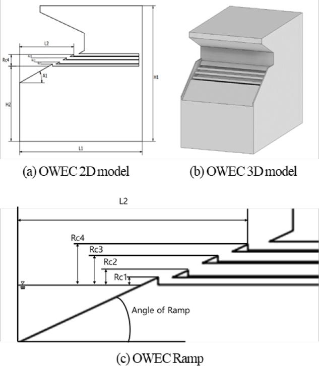
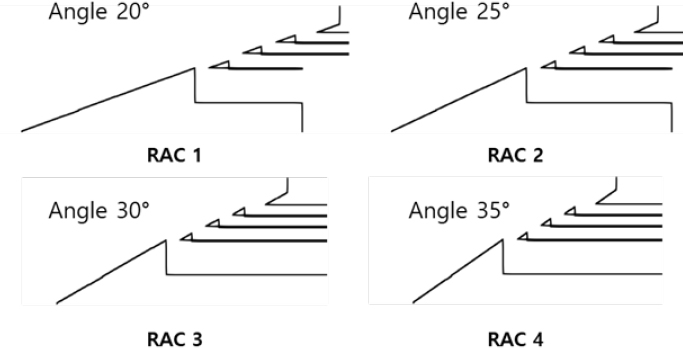
The model used in this study is identical to that used by An et al. [10]. The design and dimensions of the baseline model are illustrated in Figure 1 and detailed in Table 2. The ramp angle of the upper structure of the wave energy converter was chosen as a design variable, with the angles varying incrementally from 20° to 35° at 5° intervals. The geometries and specifications of the modified models are shown in Figure 2 and Table 3.
3.2 2D-numerical water tank
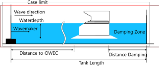
A two-dimensional numerical water tank was generated and analyzed using the SPH method. The environmental and numerical parameters of the two-dimensional water tank are illustrated in Figure 3 and summarized in Table 4.
A piston-type wave generator with a distance of 4 m between the wave generator and structure and a water depth of 0.9 m was employed. The motion of the piston-type wave generator is described as follows (Biesel and Suquet [11]):
| (9) |
The wave generator moves according to its displacement e(t) over time, where ω represents the wave frequency. δ is the initial phase, which is set to 0 in this study. S0 denotes the stroke of the wave generator, which is related to the wave height H as expressed in Equation (10).
| (10) |
The wave frequency ω is determined using the dispersion relationship for shallow water, as shown in Equation (11).
| (11) |
where d represents the water depth, and k denotes the wave number.
4. Results
4.1 Hydraulic Efficiency
The performance of the OWEC was analyzed by comparing its overtopping flow rate and energy efficiency. In this study, we utilized hydraulic efficiency, which represents the energy efficiency related to overtopping, as proposed by Margheritini et al. [12]. The equation for the hydraulic efficiency is as follows:
| (9) |
where Pcrest denotes the potential energy of the overtopped fluid. For a multistage OWEC, this is expressed as the sum of the potential energies of the fluid overtopped into each reservoir.
| (10) |
In this equation, ρ is the density of the fluid, g is the gravitational acceleration, qj represents the overtopping flow rate into the j-th reservoir, and Rc,j is the height from the sea level to the inlet of the j-th reservoir. The flow rate was measured based on the wave period used in the analysis, and the average value was adopted. Pwave represents the kinetic energy of the incident wave approaching the OWEC.
| (11) |
where c is the phase velocity of the wave, H is the wave height, d is the water depth, and k is the number of waves.
4.2 Analysis Results
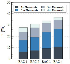
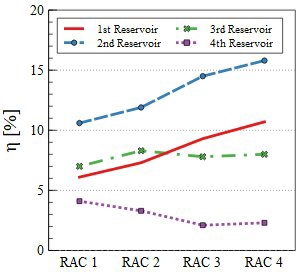
This study aims to analyze the differences in hydraulic efficiency according to changes in the ramp angle of an OWEC. The analysis results for the models with varying ramp angles are presented in Table 5 and Figure 4 and Figure 5. Additionally, Figure 6 illustrates the flow process in each reservoir over a single-wave period. Figure 6 shows that the overtopped waves enter the reservoir through two processes: ascending along the ramp and descending along the ramp.
Figure 4 shows the hydraulic efficiency of each reservoir in the models, and Figure 5 highlights the trend in the overtopping efficiency of each reservoir. As shown in Table 5, the hydraulic efficiencies of the models ranges from 30% to 37%. Overall hydraulic efficiency is highest in RAC 4, and it increases with ramp angles. Examining the changes in hydraulic efficiency by stage reveals that the efficiency of the 1st and 2nd reservoirs increases as the ramp angle becomes steeper, while the hydraulic efficiency of the 3rd and 4th reservoirs decreases with increasing ramp angle.
Although RAC 1 exhibits the lowest overall hydraulic efficiency, it demonstrates the highest hydraulic efficiency at the 4th reservoir inlet among the four models. Figure 6 shows that in the RAC 1 model, the wave’s kinetic energy in the direction of the structure is transmitted along the ramp to the 4th reservoir inlet. For RAC 1, waves primarily enter the reservoir during the ascending motion. The RAC 2 model shows a similar trend to RAC 1.
For RAC 3 and RAC 4 models with ramp angles of 30° or higher, most of the hydraulic efficiency was concentrated in the 1st and 2nd reservoirs. As shown in Figure 6, the overtopping waves in RAC 3 and RAC 4 ascend along the ramp to the 4th reservoir inlet. However, owing to the steep angles, more wave energy enters the reservoirs during the descending motion than during the ascending motion. This indicates that as the ramp angle increases, the descending waves have a greater influence on hydraulic efficiency.
The analysis results indicate that the RAC 4, with a ramp angle of 35 degrees, demonstrated the highest performance in the simulation domain. This superior performance is attributed to the increased ramp angle, which effectively concentrated wave energy into the 1st and 2nd reservoirs, maximizing energy efficiency. Notably, the steeper angle enhanced the descending wave motion, resulting in an increased inflow of water into the reservoirs. Conversely, the efficiency of the 3rd and 4th reservoirs decreased as the ramp angle increased. However, the high efficiency of the first and second reservoirs offset this decline, leading to an overall improvement in performance.
5. Conclusion
This study investigated the effect of ramp-angle variations on the energy efficiency of an OWEC. The simulation results demonstrated that the ramp angle significantly influenced a critical role in determining the hydraulic efficiency and energy distribution within the reservoirs.
As the ramp angle increased, the hydraulic efficiencies of the 1st and 2nd reservoirs showed an upward trend, whereas those of the 3rd and 4th reservoirs decreased. These findings suggest that steeper angles favor the wave energy contribution during the descending motion rather than during the ascending motion. Notably, models with ramp angles of 30° or greater exhibited most of their hydraulic efficiencies in the 1st and 2nd reservoirs.
In conclusion, the ramp angle design is a key parameter for optimizing the performance of OWECs. However, this study is based on two-dimensional simulation results. Further research involving three-dimensional simulations of the OWEC geometry is required for performance analysis, as well as model experiments to ensure the reliability of the simulation results. Additionally, the environmental conditions used in this study involved regular waves, which differ from actual conditions. Future studies should incorporate irregular waves that reflect real-world environmental conditions.
Acknowledgments
This work was supported by National R&D Program through the National Research Foundation of Korea (NRF) funded by the Korea government (Ministry of Science and ICT) (No. 2021R1I1A3057230).
Author Contributions
Conceptualization, S.-H. An and J.-H. Lee; Methodology, S.-H. An; Software, S.-H. An; Validation, S.-H. An and J.-H. Lee; Formal Analysis, S.-H. An; Investigation, S.-H. An; Resources, S.-H. An; Data Curation, S.-H. An; Writing—Original Draft Preparation, S.-H. An; Writing—Review & Editing, J.-H. Lee; Visualization, S.-H. An; Supervision, J.-H. Lee; Project Administration, J.-H. Lee; Funding Acquisition, J.-H. Lee.
References
- J. P. Kofoed, Wave Overtopping of Marine Structures Utilization of Wave Energy, Ph. D. Dissertation, Aalborg University, Aalborg, Denmark, 2002.
-
L. Victor, P. Troch, and J. P. Kofoed, “On the effects of geometry control on the performance of overtopping wave energy converters,” Energies, vol. 4, no. 10, pp. 1574-1600, 2011.
[https://doi.org/10.3390/en4101574]

- S. Jungrungruengtaworn, R. Reabroy, N. Thaweewat, and B. S. Hyun, “Numerical and experimental study on hydrodynamic performance of multi-level OWEC,” Ocean Systems Engineering, vol. 10, no. 4, pp. 359-371, 2020.
-
A. S. De Barros, C. Fragassa, M. D. S. Paiva, L. A. Rocha, B. N. Machado, L. A. Isoldi, and E. D. dos Santos, “Numerical study and geometrical investigation of an onshore overtopping device wave energy converter with a seabed coupled structure,” Journal of Marine Science and Engineering, vol. 11, no. 2, 412, 2023.
[https://doi.org/10.3390/jmse11020412]

-
D. Cao, J. He, and H. Chen, “Empirical predictions on wave overtopping for overtopping wave energy converters: a systematic review,” Processes, vol. 12, no. 9, 1940, 2024.
[https://doi.org/10.3390/pr12091940]

-
S. A. Da Silva, J. C. Martins, E. D. dos Santos, L. A. O. Rocha, B. N. Machado, L. A. Isoldi, and M. das Neves Gomes, “Constructal design applied to an overtopping wave energy converter locate on Paraná Coast in Brazil,” Sustainable Marine Structures, vol. 6, no. 2, pp. 1-14, 2024.
[https://doi.org/10.36956/sms.v5i2.1113]

-
G. G. Kim, S. H. An, and J. H. Lee, “Review of the optimal locations of coastal sea area for operating wave energy converter in Korea,” Journal of Advanced Marine Engineering and Technology, vol. 46, no. 4, pp. 172-181, 2022.
[https://doi.org/10.5916/jamet.2022.46.4.172]

-
J. J. Monaghan, “Smoothed particle hydrodynamics,” Annual Review of Astronomy and Astrophysics, vol. 30, pp. 543-574. 1992.
[https://doi.org/10.1146/annurev.astro.30.1.543]

-
J. J. Monaghan, R. A. Cas, A. M. Kos, and M. Hallworth, “Gravity currents descending a ramp in a stratified tank,” Journal of Fluid Mechanics, vol. 379, pp. 39-69, 1999.
[https://doi.org/10.1017/S0022112098003280]

-
S. H. An, J. H. Lee, G. G. Kim, and D. H. Kang, “Optimal design of overtopping wave energy converter substructure based on smoothed particle hydrodynamics and structural analysis,” Journal of the Korean Society of Marine Environment & Safety, vol. 29, no. 7, pp. 992-1001, 2023.
[https://doi.org/10.7837/kosomes.2023.29.7.992]

- F. Biesel and F. Suquet, “Etude theorique d'un type d'appareil a la houle. La Houille Blanche,” vol. 6, no.2, pp. 152-165, 1951.
-
L. Margheritini, D. Vicinanza, and P. Frigaard, “SSG wave energy converter: Design, reliability and hydraulic performance of an innovative overtopping device,” Renewable Energy, vol. 34, no. 5, pp. 1371-1380, 2009.
[https://doi.org/10.1016/j.renene.2008.09.009]


