Two-dimensional camera and TOF sensor-based volume measurement system for automated object volume measuring
Copyright © The Korean Society of Marine Engineering
This is an Open Access article distributed under the terms of the Creative Commons Attribution Non-Commercial License (http://creativecommons.org/licenses/by-nc/3.0), which permits unrestricted non-commercial use, distribution, and reproduction in any medium, provided the original work is properly cited.
Abstract
In smart systems such as smart factories and smart logistics centers, vision inspection or volume measurement automation systems that reverify the damage status and size of products are essential. Existing methods have limitations in that they use many sensors for development or require a large installation space, which results in high construction costs. Therefore, in this study, we propose an object-volume measurement system based on image segmentation using a two-dimensional (2D) camera and a time-of-flight (TOF) sensor. The proposed system captures product images using a 2D camera and determines the pixel area of the product using an image-segmentation model. The height of the product is then obtained using a TOF sensor, and the horizontal and vertical lengths of the object are output through a conversion equation that converts one pixel to millimeters based on the height information. The proposed system has the advantage of low construction costs because it does not require expensive equipment such as 3D cameras or radio detection and ranging (RADAR) and can be easily installed in various environments. Thus, it is possible to easily build a volume measurement system, even with a limited structure, contributing to logistics automation.
Keywords:
Volume measurement, Image segmentation, Computer vision, Deep learning1. Introduction
With the development of technologies such as artificial intelligence and robotics, process automation solutions [1]-[4] have been distributed to automated facilities such as smart factories and smart logistics centers. Among these, volume measurement technology [5]-[7] can achieve automation in processes such as optimizing the loading space and billing delivery costs by identifying the physical specifications of the target product. If these processes are automated, incorrect delivery, damage, and cost losses that occur during the logistics process can be prevented. In addition, when a customer receives product delivery in the last mile, vision inspection is a key technology that automatically receives the physical information of the product and enables quick delivery. Thus, if a vision inspection technology for measuring the volume of a product is developed, the waste of submission costs caused by manpower and errors in the verification and submission steps can be reduced.
The dimensions, weighting, and scanning (DWS) system is representative of the volume measurement equipment. The DWS system measures the volume and weight of products on the conveyor belt and scans the codes attached to the products. DWS systems use several cameras or laser sensors to measure the volume of a product. However, the application of a DWS system incurs high costs, because it requires many sensors. Moreover, because it requires a large installation space, it has the disadvantage of being difficult to use for reception process in the last-mile stage. In addition, lighting is not constant for measuring the volume at the dealership accepting the parcel, making it difficult to measure using only an image-processing algorithm that uses the differences between pixels. Therefore, to use the volume measurement system in the last-mile stage, we must consider the characteristics of minimizing environmental influences and ease of construction.
Image segmentation is a technology that determines the pixel-level area of the target to be detected and can accurately determine the horizontal and vertical information of an object from an image captured by a 2D camera [8]-[10]. Additionally, a TOF sensor can emit light to an object and measure the distance through the returning light and obtain information about the height. Therefore, if a volume measurement system is built by combining a 2D camera and TOF sensor costs are minimized. Moreover, if data that varies depending on lighting to learn a deep learning-based image segmentation model is used, the area of the object can be determined accurately even under the influence of lighting.
In this study, we propose a volume measurement system that measures the volume of an object using only a small space, 2D camera, and Time-of-Flight TOF) sensor. The proposed system measures the volume using only a 2D camera from above the floor and a TOF sensor. The image collected from the 2D camera was used to determine the pixel area of the object using an object-segmentation module. The proposed system uses a TOF sensor to determine the height of an object. Finally, we propose a conversion equation that converts the height obtained from the TOF sensor into the actual pixel length and calculates the actual horizontal and vertical lengths. The segmentation module of the proposed system identifies objects using YOLACT [10], a lightweight model, to accurately determine the pixel area of the object. In addition, because the system can be built using only low-cost sensors, it has the advantage of a low construction cost.
The remainder of this paper is organized as follows: Section 2 explains the trends in related research on existing volume measurement methods; Section 3 discusses the proposed system in detail. In Section 4, a verification is performed using test objects to evaluate the performance of the proposed system, and Section 5 presents the conclusions.
2. Related Works
2.1 Image-based Volume Measurement Method
Image-based volume measurement is a method of measuring the length by finding the pixel area of the target in image data and converting it to actual units. In the medical field, image segmentation is used to detect abnormal areas in photographs of the human body and calculate their size, such as using image segmentation to find tumors in the brain or liver and estimate their length [11]-[12]. Moreover, in architecture, previous studies have investigated methods for finding cracks and calculating their length using image segmentation [13]-[14] or methods for estimating the volume of a sample [15]. In the studies, the priority was to find the target using image segmentation, and because the actual length of the pixel is fixed in length estimation methods, it is not considering various reference heights when measuring the volume of an object.
The existing research on methods for measuring object volume by collecting images with a camera is as follows: Won et al. proposed a method for measuring the size of an object by installing a camera at a set distance, detecting the outer line of a rectangular object using edge detection, and determining the vertex [16]. This method can measure the width, length, and height of a rectangular object using only a 2D camera; however, it is applicable only to square objects and has the disadvantage of making accurate edge detection difficult if the color of the object is similar to that of the background. Hong et al. [17] proposed a method for estimating the volume of a pear by placing four multi-depth cameras on the side. However, this method has the disadvantage of high construction costs because it uses four multi-depth cameras. Khojasthnazhand et al. determined the maturity of photographed apricots using volume estimation [18]. The background and noise were removed from apricot images captured with a camera, and the features obtained through feature extraction were analyzed using latent Dirichlet allocation (LDA) [19] and quantitative descriptive analysis (QDA) [20]. However, this method has the disadvantage that the lighting and background are fixed in the video shooting environment; therefore, the proposed algorithm cannot be applied in the same order. Therefore, to disseminate automatic volumetric measurement systems to various fields and locations, research on methods that are robust against lighting changes with low construction costs is required.
3. Proposed System
3.1 Structure of the Proposed System
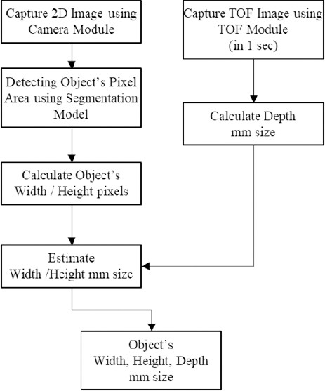
The hardware of the proposed system was designed using cameras and TOF sensors arranged to capture the target from the top to bottom. The flow of the designed volume measurement system is shown in Figure 1.
First, the system captured 2D and TOF images from the camera and TOF modules. To minimize sensor errors, TOF images were captured for 1 s, and the average was calculated. For 2D images, the pixel area of the object was extracted using the segmentation model, and the width and height of the object in pixel units were obtained by defining the border as a square from the result of detecting only the pixel area.
In the 2D depth data array obtained from the TOF image, the value of the portion occupied by the target was obtained using the size difference from the floor surface to obtain the depth results in millimeters. To convert the pixel values of the width and height into actual length units, we estimated their millimeter values by substituting the detected depth into a pixel-to-millimeter conversion formula. The pixel-level conversion formula was obtained by applying curve fitting to the pixels captured by the camera to the height measured by the TOF sensor, as described in detail in Section 3.3. In the following sections, the process of obtaining the width and height of the object in each flow of the proposed system is explained, and the process of obtaining the height using a TOF image and converting the length in pixels to actual units is described in detail.
3.2 Process of acquiring the Width and Height Pixel of an Object using a 2D Camera
Existing methods involve the extraction of the physical information of a target using image-processing algorithms in a designated image-shooting environment. The disadvantage of these methods is that, if the lighting or surrounding environment changes during filming, the parameters of the image-processing algorithms must be adjusted accordingly. To address this short-coming, this study uses a deep-learning-based image segmentation method to extract the physical information of the objects. The process of acquiring pixel information through image segmentation using the proposed system is illustrated in Figure 2.
First, the captured box image was input into the segmentation model to obtain pixel-level results. In the proposed system, we used YOLACT, a light-weight deep-learning model, as the segmentation model to achieve fast processing. YOLACT learns the pixel output of an object and outputs the pixel area. The data used for learning included a dataset constructed in various lighting environments to achieve a robust effect against lighting changes. The segmentation output obtains edge information using the Canny algorithm, an edge-detection algorithm that defines the outline using the Hough transform and defines the object area as a rectangle with the MinareaRect function in OpenCV. The system then determines the width and height of an object based on the width and height of the defined square.
3.3 Depth Acquisition Process using the TOF Module
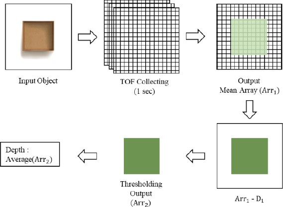
The proposed system uses a TOF module to obtain actual information regarding the depth of the target and physical information to convert pixels into actual length units. The TOF module is responsible for using the TOF sensors and processing their data. A TOF sensor measures distance by measuring the time required to emit light, reflect it, and return it. This is inexpensive and enables quick data acquisition. The process of acquiring the depth in the proposed system is shown in Figure 3.
When an object was placed in front of the TOF module, as shown in Figure 3, the TOF data were collected for 1 s. The size of the measured array varied depending on the resolution of the sensor, and sensor error was minimized by collecting data for 1 s. Then, Arr1 was obtained by calculating the average of the array collected for 1 s. The height of the object was obtained by subtracting it from the height at which the TOF sensor was installed (D1). From the array obtained in this manner, through thresholding, it was possible to obtain Arr2, which had only the height of the object area, and the rest was zero by excluding the low value judged as the floor. Finally, the depth was estimated by calculating the average of the nonzero values in Arr2.
3.4 Estimation of the Millimeter Size using the Pixel-To-Millimeter Conversion Formula
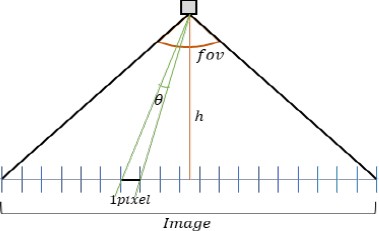
When the physical information of a target is identified in pixel units, it is converted into actual length units. In this study, we proposed a millimeter-per-pixel conversion formula using the distance to the target and FOV of the TOF sensor, and applied it to length conversion. The relationship between the distance to the target, FOV of the TOF sensor, and pixel-to-millimeter conversion is shown in Figure 4.
In Figure 4, assuming the maximum angle fov that the TOF sensor is shooting and the height between the camera and the floor is h, the equation for the shooting angle θ of the TOF image for one pixel of the captured image is
| (1) |
Using the image angle θ and height h occupied by one pixel, the length ratio of one pixel can be obtained using Equation (2),
| (2) |
Using this method, we obtained the pixel of the image and converted it to millimeters by multiplying it by the horizontal and vertical pixels of the object. This method has the advantage of not requiring other calibration tasks because the same formula can be applied depending on the height of the camera.
4. Results
4.1 Experimental Settings
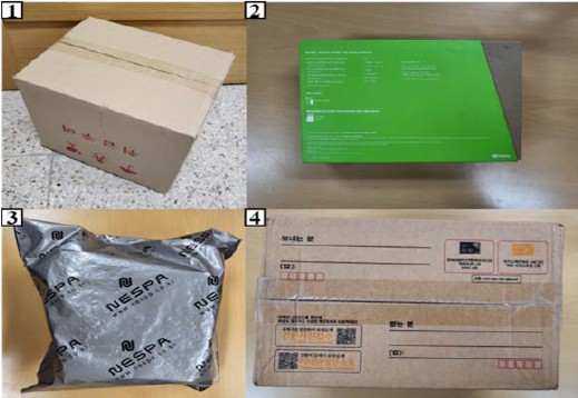
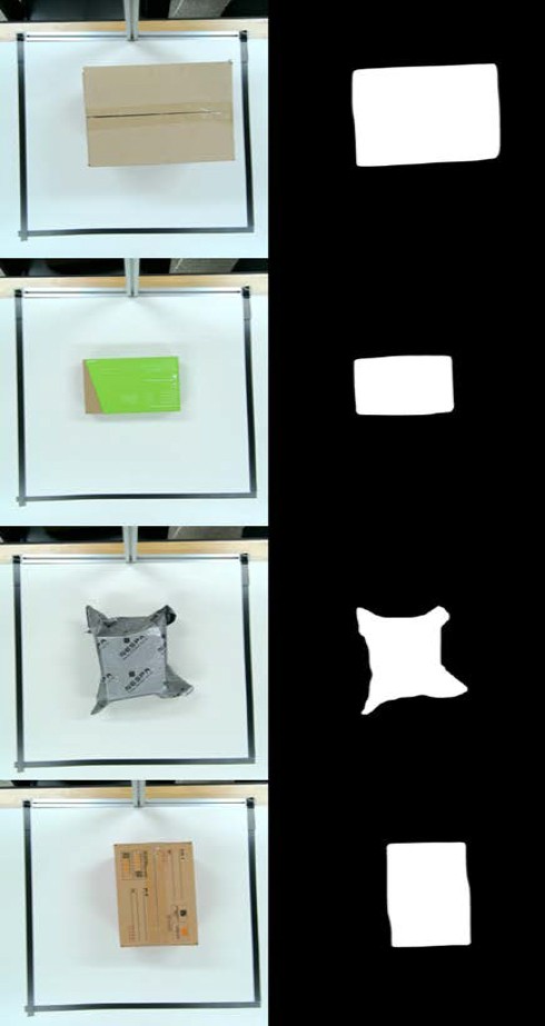
To evaluate the performance of the proposed system, a hardware 2D camera of the volume measurement system used a 4K wide-angle camera sensor, and a TOF camera used a TOF sensor that receives 8 × 8 data in the height at which the volume-measurement module was installed is 850 mm, and a white board was used as the floor to place the object to be measured. The computing device used for the measurement was a Jetson Xavier NX, an edge-computing device, and it was verified in two cases: when all the lights were turned on indoors and when half of the lights were turned off. The objects used in the test were post office boxes (mainly used for delivery reception), boxes of various colors, and boxes wrapped in plastic. In the case of a box wrapped in plastic, the physical information included the maximum width and height. The height was determined by measuring the maximum value and height of the box inside and determining the height as the median value. The objects used in the tests are shown in Figure 5.
In this study, we collected and trained the YOLACT learning dataset, which was used as the segmentation model. The dataset consisted of 8,000 images collected from four different locations with different lighting on eight objects. Among the collected images, 6,000 were used for learning, 1,000 for verification, and 1,000 for testing.
4.2 Result and Discussion
To compare the volume measurement performance of the proposed system, each test object was measured five times, and the error, which is the difference between the average length and ground truth, and mean average precision (mAP) of the segmentation output were compared. The mAP is the union divided by the intersection of the predicted segmentation result and the ground truth, and is a representative indicator that evaluates whether the pixel area is accurately predicted. Table The quantitative results are shown in Table 1 below.
According to Table 1, most of the predicted results were accurately output within an error range of 10 mm. The area with the largest error was the height of vinyl object 3; however, an error exists in the estimation because the shape is more complex. This is discussed in detail later, along with an analysis of the segmentation results shown in Figure 6. Although the depth depends on the performance of the TOF sensor, the depth of an object can be measured within 10 mm. In addition, the pixel area was found to have a high accuracy, even in the mAP metric. Images of the segmentation results are shown in Figure 6.
The segmentation results also show that the pixel area was accurately determined despite lighting effects such as shadows and reflections. When compared with the quantitative comparison results for each object in Table 1, the segmentation results show that the mAP for the box was 97–98%, and that for unstructured Object 3 was the lowest at 96%. Based on these results and comparing them with the results in Table 1 show a 30-pixel difference in height when comparing the prediction results of Object 3 in terms of pixel results. However, for Object 3, which had similar heights, the pixel difference in height was as low as eight pixels. Therefore, the height error of Object 3, which is an atypical vinyl, was as large as 32 mm. In addition, to analyze the overall height error, we compared the width and height pixel errors of the segmentation output for the test case. Consequently, the width pixel error was 1–12 pixels on average, and the area was accurately determined. However, the height pixel error was 12–30 pixels, which shows that the error was larger than that of the width. Although it was found that the error was large according to the segmentation results, further research is required to improve the segmentation performance of small areas to solve this problem.
In addition, the average time required to obtain the segmentation results was long (7.5 s). This is because the resolution of the image being processed was 4K; thus, the capacity of the image was large. Even if the image is lowered to FHD quality, it is believed that fast processing within 0.3 swill be possible with similar segmentation performance. In addition, if the system is processed on a server, this problem can be solved because high-performance equipment can be used.
We then compared the performance of the proposed system with those of similar previous studies and products. We compared Won et al. [16], Hong et al. [17], and CLIS-500 [21], which can measure irregular volumes using a camera sensor from CASS. Because all three methods measure the volume of an object using a camera sensor, they were judged to be appropriate for performance comparison. CLIS-500 can measure objects through 3D scanning using a structured light (SL) camera. Table 2 shows the comparison results between the proposed system and the comparative models.
In Table 2, a regular object is an object that can accurately measure the width, length, and height of a rectangular parallelepiped, such as a box, whereas an irregular object is a shape other than a rectangular parallelepiped and an object that is easily deformed, such as a vinyl object. According to the result comparison, the regular measurement error of the proposed system is ±12 mm, which is the largest, compared to the other three cases. Won et al. had the smallest formal measurement performance at ±6 mm; however, this method cannot measure dimensions of irregular objects and is limited by the camera installation location and lighting conditions. Therefore, it cannot be considered suitable as a volume measurement system for use in the last mile stage. In irregular measurements, the measurement error of the proposed system was ±32 mm, whereas it was the lowest (±15.5 mm) in Hong et al. [17]. However, because this method uses four expensive stereo cameras, the construction cost is high, making it difficult to build many systems. Lastly, CLIS-500 performed similarly to the proposed system and had an irregular measurement performance of ±20 mm, which was more accurate than the proposed system, but the SL camera used is more expensive than a 2D camera. In addition, lighting must be fixed, making it difficult to use outdoors or in indoor areas close to the outdoors. The proposed system had a lower measurement performance than the other models; however, the system can be built for less than 150,000 won using only low-cost sensors. Thus, it is a suitable volume measurement system for delivery reception and storage boxes that require mass manufacturing.
5. Conclusion
In this study, we proposed an object-volume measurement system that uses only a 2D camera and TOF sensor. The proposed system photographs the upper surface of the target using the 2D camera to obtain the horizontal and vertical pixel areas as well as the depth of the target using the TOF sensor. The proposed system determined the pixel area of the target using YOLACT, an image segmentation model, and could accurately determine the pixel area of the target, even in reflections and shadows, owing to lighting effects. Then, using the depth of the target and FOV of the TOF sensor, the actual horizontal and vertical lengths were obtained using a formula for converting the image pixels into millimeters. To evaluate the performance of the proposed system, four test objects were selected and their accuracy was analyzed. It was confirmed that they showed a high estimation accuracy of less than 10 mm for each side. The segmentation model used in the proposed system was trained using a self-constructed dataset and achieved high performance in the mAP verification of the test images. However, real-time processing of high-definition, high-capacity images is time-consuming. To solve this problem, we plan to conduct research on a system capable of fast processing, even with high-definition quality, by conducting research on segmenting only the necessary areas.
Acknowledgments
This work was supported by Institute of Information & communications Technology Planning & Evaluation (IITP) grant funded by the Korea government (MSIT) (No. RS-2023-00254240, Development of non-face-to-face delivery of postal logistics and error verification system for parcel receipt.). This work was supported by the National Research Foundation of Korea (NRF) grant funded by the Korea government (MSIT) (No. NRF-2021R1A2C1014024).
Author Contributions
Conceptualization, J. W. Bae and J. H. Seong; Methodology, J. W. Bae and D. H. Seo; Software, J. W. Bae; Data Curation, J. W. Bae; Writing—Original Draft Preparation, J. W. Bae; Writing— Review & Editing, D. H. Seo and J. H. Seong; Supervision, J. H. Seong;
References
-
S. W. Oh, C. H. Lee, S. M. Kim, D. J. Lim, and K. B. Lee, “A novel multi-object distinction method using deep learning,” The Transactions of the Korean Institute of Electrical Engineers, vol. 70, no. 1, pp. 168-175, 2021 (in Korean).
[https://doi.org/10.5370/KIEE.2021.70.1.168]

-
J. U. Won, M. H. Park, S. W. Park, J. H. Cho, and Y. T. Kim, “Deep learning based cargo recognition algorithm for automatic cargo unloading system,” Journal of Korean Institute of Intelligent Systems, vol. 29, no. 6, pp. 430-436, 2019 (in Korean).
[https://doi.org/10.5391/JKIIS.2019.29.6.430]

-
X. Zhao and C. C. Cheah, “BIM-based indoor mobile robot initialization for construction automation using object detection,” Automation in Construction, vol. 146, p. 104647, 2023.
[https://doi.org/10.1016/j.autcon.2022.104647]

-
T. Huang, K. Chen, B. Li, Y. H. Liu, and Q. Dou, “Demonstration-guided reinforcement learning with efficient exploration for task automation of surgical robot,” 2023 IEEE International Conference on Robotics and Automation (ICRA), London, United Kingdom, pp. 4640-4647, 2023.
[https://doi.org/10.1109/ICRA48891.2023.10160327]

- Q. Chen, Y. Zhou, and C. Zhou, “The research status and prospect of machine vision inspection for 3D concrete printing,” Journal of Information Technology in Civil Engineering and Architecture, vol. 15, no. 5, pp. 1-8, 2023.
-
D. Lee, G. Y. Nie, and K. Han, “Vision-based inspection of prefabricated components using camera poses: Addressing inherent limitations of image-based 3D reconstruction,” Journal of Building Engineering, vol. 64, p. 105710, 2023.
[https://doi.org/10.1016/j.jobe.2022.105710]

-
Y. Lyu, M. Cao, S. Yuan, and L. Xie, “Vision-based plane estimation and following for building inspection with autonomous UAV,” IEEE Transactions on Systems, Man, and Cybernetics: Systems, vol. 53, no. 12, pp. 7475-7488, 2023.
[https://doi.org/10.1109/TSMC.2023.3299237]

- S.Minaee, Y. Boykov, F. Porikli, A. Plaza, N. Kehtarnavaz, and D. Terzopoulos, “Image segmentation using deep learning: A survey,” IEEE Transactions on Pattern Analysis and Machine Intelligence, vol. 44, no. 7, pp. 3523-3542, 2022.
-
C. Yu, J. Wang, C. Peng, C. Gao, G. Yu, and N. Sang, “Bisenet: Bilateral segmentation network for real-time semantic segmentation,” in Proceedings of the European Conference on Computer Vision (ECCV), pp. 334-349, 2018.
[https://doi.org/10.1007/978-3-030-01261-8_20]

-
D. Bolya, C. Zhou, F. Xiao, and Y. J. Lee, “Yolact: Real-time instance segmentation,” in Proceedings of the IEEE/CVF international conference on computer vision, pp. 9156-9165, 2019.
[https://doi.org/10.1109/ICCV.2019.00925]

-
P. Zheng, X. Zhu, and W. Guo, “Brain tumour segmentation based on an improved U-Net,” BMC Medical Imaging, vol. 22, no. 1, pp. 1-9, 2022.
[https://doi.org/10.1186/s12880-022-00931-1]

-
S. Saha Roy, S. Roy, P.Mukherjee, and A. Halder Roy, ”An automated liver tumour segmentation and classification model by deep learning based approaches,” Computer Methods in Biomechanics and Biomedical Engineering: Imaging & Visualization, vol. 11, no. 3, pp. 638-650, 2023.
[https://doi.org/10.1080/21681163.2022.2099300]

-
S. M, Lee, G. Y. Kim, and D. J. Kim, “Development of robust crack segmentation and thickness measurement model using deep learning,” The Journal of Korean Institute of Communications and Information Sciences, vol. 48, no. 5, pp. 554-566, 2023 (in Korean).
[https://doi.org/10.7840/kics.2023.48.5.554]

-
L. Barazzetti and M. Scaioni, “Crack measurement: Development, testing and applications of an automatic image-based algorithm,” ISPRS Journal of Photogrammetry and Remote Sensing, vol. 64, no. 3, pp. 285-296, 2009.
[https://doi.org/10.1016/j.isprsjprs.2009.02.004]

-
M. Kamari and Y. Ham, “Vision-based volumetric measurements via deep learning-based point cloud segmentation for material management in jobsites,” Automation in Construction, vol. 121, p. 103430, 2021.
[https://doi.org/10.1016/j.autcon.2020.103430]

- J. W. Won, Y. S. Chung, W. S. Kim, K. H. You, Y. J. Lee, and K. H. Park, “A single camera based method for cubing rectangular parallelepiped objects,” Journal of KIISE: Computing Practices and Letters, vol. 8, no. 5, pp. 562-573, 2002.
-
S. J. Hong, A. Y. Lee, and J. S. Kim, “Development of real-time 3D reconstruction and volume estimation technology for pear fruit using multiple depth cameras,” Journal of the Korea Academia-Industrial Cooperation Society, vol. 24, no. 10, pp. 1-8, 2023.
[https://doi.org/10.5762/KAIS.2023.24.10.1]

-
M. Khojastehnazhand, V. Mohammadi, and S. Minaei, “Maturity detection and volume estimation of apricot using image processing technique,” Scientia Horticulturae, vol. 251, pp. 247-251, 2019.
[https://doi.org/10.1016/j.scienta.2019.03.033]

- D. M. Blei, A. Y. Ng, and M. I. Jordan, “Latent dirichlet allocation,” Journal of Machine Learning Research, pp. 993-1022, 2003.
-
J. L. Sidel, R. N. Bleibaum, and K. W. Clara Tao, “Quantitative descriptive analysis,” Descriptive Analysis in Sensory Evaluation, pp. 287-318, 2018.
[https://doi.org/10.1002/9781118991657.ch8]

- CAS, https://www.cas.co.kr/integration/read.jsp?reqPageNo=1&code=20200624a1d20b0cce&no=207, , Accessed December 19, 2023.

