Prediction method for shape drawing force considering redundant deformation
Copyright © The Korean Society of Marine Engineering
This is an Open Access article distributed under the terms of the Creative Commons Attribution Non-Commercial License (http://creativecommons.org/licenses/by-nc/3.0), which permits unrestricted non-commercial use, distribution, and reproduction in any medium, provided the original work is properly cited.
Abstract
A prediction method for shape-drawing force was developed with the cross-section division method, which divides the cross-sections of the initial workpiece and final product into finite elements at small angles. Each divided element is assumed to undergo an axisymmetric drawing process. Wistreich’s equation, which considers redundant deformation by employing a redundant work factor, was applied to calculate the axisymmetric drawing force for each element. To evaluate the redundant work factor, which varies with the reduction ratio and half die angle, a regression equation between the redundant work factor and a geometric parameter associated with the die’s deformation zone was derived by performing a finite element (FE) analysis on a series of axisymmetric drawing processes. The validity of the proposed method was confirmed via FE analysis of various shape-drawing processes. The forming load predicted by the proposed method exhibited good agreement with the results of the FE analysis, with errors of approximately 10% or less.
Keywords:
Shape drawing force, Cross-section division method, Wistreich’s equation, Redundant work factor, Finite element analysis1. Introduction
Drawing is a cold-forming process that involves pulling wires, rods, or bars via a die to reduce its cross-sectional area while increasing its length [1]. This process offers superior surface finish and nearnet-shaped dimensions in long products with constant arbitrary cross-sections [2]. Recently, there has been a significant increase in the production of machine parts with complex cross-sectional profiles via drawing processes that are not limited to axisymmetric profiles. This shape-drawing process has various applications in several fields, including automotive, semiconductor, robotic, and precision measurement devices [3].
Theoretical analysis of the drawing force has been an important issue over the last few decades because it is closely related to practical concerns, such as determining whether it is feasible to draw a part under specific conditions and whether the final product will maintain the desired dimensional accuracy. Numerous studies have been conducted to calculate the drawing force, primarily based on the slab method [4], upper-bound method [5], and finite element (FE) method [6][7]. These investigations predominantly focused on the axisymmetric drawing process, which involves shaping round sections from round bars. However, only a few researchers have evaluated the forming load during the shape-drawing process. Basily and Sansome [8] proposed upper- and lower-bound solutions for predicting the drawing force when shaping symmetric section rods from a round stock. Lee et al. [9] introduced a straightforward approach to estimating the forming load during the drawing process for arbitrary cross-sectional shapes by employing the cross-sectional division method and Geleji’s equation, an analytical model of the axisymmetric drawing force. Furthermore, Kim et al. [10] expanded this method to draw force predictions in a multistage drawing process incorporating idle roll dies. However, it has also been reported that the existing approach employing Geleji’s equation can result in significant errors of approximately 30% [11].
The main objective of this study was to propose an analytical method for evaluating the forming force required to create components with complicated cross-sectional profiles via the shape-drawing process. This goal is achieved by employing the cross-sectional division method [9], assuming that the divided finite elements of the initial and final cross-sectional shapes are deformed like an axisymmetric drawing process. In addition, Wistreich’s equation [12], in which the effect of redundant deformation on the drawing force is considered by applying a redundant work factor, was applied to calculate the drawing force for each divided element. Because the redundant work factor varies across the cross-section owing to changes in the deformation zone geometry of the die in shape drawing, FE analysis was utilized to establish the correlation between the redundant work factor and a geometric parameter of the die deformation zone. Finally, the shape-drawing processes are simulated via FE analysis to validate the applicability of the developed prediction model for the shape-drawing force.
2. Drawing Force Prediction Model
2.1 Analytical Model for Shape Drawing
Figure 1 schematically illustrates the cross-sectional division method. The first step involves dividing the cross-sections of the initial and final products into finite elements at a small angle (θ). Each divided element can be treated as an axisymmetric drawing process, where the inlet and exit radii are denoted as R(i,i) and R(o,i), respectively, and αi is the half-die angle. Subsequently, the drawing force for an element (Fd,i) was computed with a theoretical model for axisymmetric drawing. Finally, the total shape drawing force (Fd,total) was determined by summing the drawing forces from each divided element as follows.
| (1) |
where n is the number of total elements.
According to Wistreich [12], the analytical solution for the axisymmetric drawing force (Fd) can be expressed as
| (2) |
where Φ is the redundant work factor; A2 is the cross-sectional area of the die outlet; Ym is the mean yield stress; μ is the friction coefficient; α is the half die angle. εh is the homogeneous strain defined by
| (3) |
where A1 represents the cross-sectional area of the die inlet. For a material with a strain-hardening behavior following a power law, the mean yield stress is given by
| (4) |
where K is the strength coefficient of the material, and m is the strain hardening exponent.
In Equation (2), Ymεh represents the drawing force for homogeneous deformation. The term μcotα reflects the additional force required to overcome the friction between the material and the die. The redundant work factor Φ relates to the internal distortion of the material, which does not contribute to the dimensional change but induces a redundant strain other than that required for homogeneous deformation [13]. Φ can be determined experimentally by measuring the drawing force and dividing it by the term A2Ym(1+μcotα)εh which is denoted as FI hereafter. The drawing force FI can be readily calculated, provided the friction coefficient and the stress–strain relationship are known. Generally, it is believed that Φ depends on a single geometric parameter of the die’s deformation zone, namely Parameter Δ, which can be given by Equation (5) [13]:
| (5) |
where r is the reduction ratio between the initial shape and the final one.
Because the cross-section division method assumes that shape drawing comprises multiple axisymmetric drawing processes with different reduction ratios and half-die angles, it is essential to establish a general relationship between Φ and Δ. This allows the redundant work factor associated with a specific Δ to be estimated easily across a wide range of scenarios. To derive an analytical expression for the redundant work factor Φ, Atkins and Caddell [14] conducted extensive axisymmetric drawing tests on stainless steel and aluminum and found that a linear equation could be formulated between Φ and Δ. However, drawing tests for all conditions in question can be impractical and time-consuming. Therefore, here, FE analysis was conducted on axisymmetric drawing involving diverse combinations of reduction ratios and half-die angles to investigate the relationship between the redundant work factor and the parameter Δ.
2.2 Evaluation of Redundant Work Factor
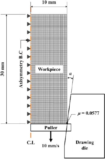
Rigid-plastic analysis for axisymmetric drawing was conducted via the commercial forming analysis software DEFORM 2D. Table 1 presents the 20 values for the parameter Δ that were chosen for FE analysis, considering the typical ranges of half-die angles and reduction ratios utilized in shaped drawing [1]. Figure 2 illustrates the FE analysis model. The initial workpiece was 30-mm long and 20-mm in diameter. A total of 6,030 elements were employed, with a minimum element size of approximately 0.22 mm. Regarding the equipment specifications typically utilized in the industrial field, a drawing speed of 10 mm/s was utilized, and the friction coefficient μ between the material and die was set to 0.0577, as per previous research [10].
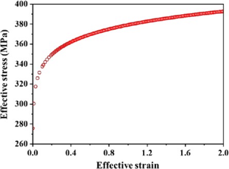
The material under investigation was a highly pure stainless steel (STS 316L) manufactured via a two-stage vacuum melting process that included vacuum induction melting and vacuum arc remelting. Mechanical properties were determined via uniaxial tensile tests conducted in accordance with the KS B 0802 standard. The tensile test specimens had a gauge length of 25 mm and a diameter of 5 mm. The mechanical properties obtained from the tests are presented in Table 2, and Figure 3 illustrates the flow-stress curve employed for the FE analysis.
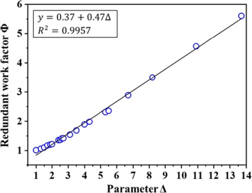
The drawing forces evaluated by FE analysis for various Δ values are presented in Table 3, along with the theoretically calculated drawing forces (referred to as FI) that do not consider the contribution of redundant deformation. The redundant work factor Φ was subsequently determined by comparing the FE analysis results with the corresponding drawing force, FI. The values of Φ as a function of Δ are presented in Figure 4. It is noteworthy that, similar to the results obtained from the literature [14], all Φ values for the experimental material exhibit a dependence on Δ, which leads to the following linear regression equation.
| (6) |
With the established relationship between Φ and Δ for the material described in Equation 6, Wistreich’s equation can now be applied to predict the forming load in drawing processes that create products with arbitrary cross-sectional shapes.
3. Shape Drawing Force Evaluation
3.1 FE Analysis Conditions
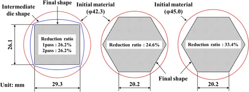
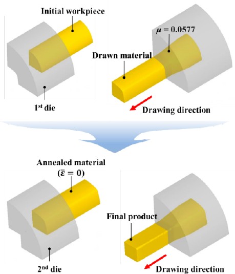
The drawing force prediction method proposed here was verified via an FE analysis of various shape-drawing processes. Figure 5 presents the cross-sectional profiles of the final products with rectangular and hexagonal shapes manufactured from the round initial bars. To prevent undercutting, the diameter of the initial material was set to be larger than the minimum circumference of the product. For the rectangular profile, a multistage drawing process was implemented, which included an intermediate heat treatment owing to the substantial reduction ratio of 45.6%. Therefore, to consider the effect of heat treatment, the effective strain accumulated in the material after 1st pass drawing was set to zero when a 2nd pass forming analysis was performed, as depicted in Figure 6. The intermediate die shape of the multistage drawing process (i.e., the final shape of the 1st pass) was determined via electric field analysis [15]. In addition, a pass schedule was designed based on the average reduction ratio (ravg), defined as follows.
| (7) |
where rtotal is the total reduction ratio, and p is the number of passes.
Considering the symmetry of all final products, a quarter-section was analyzed with DEFORM 3D software, as demonstrated in Figure 6. The analysis utilized approximately 140,000 and 95,000 3D tetrahedral elements for multistage rectangular shape drawing and hexagonal shape drawing, respectively. The minimum element size was 0.14 mm for the former and 0.84 mm for the latter. The material properties and analysis conditions, such as drawing speed and friction coefficient, were consistent with those utilized in the FE analysis of the axisymmetric drawing process, as detailed in Section 2.2.
3.2 Results of Drawing Force Prediction
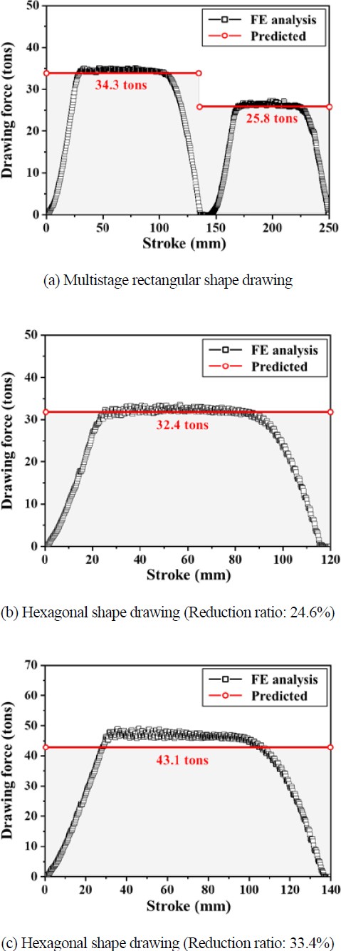
Figure 7 compares the drawing forces predicted by the proposed method and those obtained via FE analysis. The cross-section division method was employed for the evaluation utilizing the proposed method, involving the division of cross-sectional profiles into 30 elements with an angle (θ) of 3°. Following this, the redundant work factor for each divided element was computed with Equation (6) based on the reduction ratio and halfdie angle (i.e., parameter Δ). Finally, Wistreich’s equation was applied to predict the drawing force for each divided element, and the overall drawing force was determined by combining the drawing forces of all the elements.
The values of the drawing forces and associated errors of the proposed method are compared with the results obtained from the FE analysis in Table 4. For comparison, the drawing forces estimated by the method proposed by Lee et al. [9] utilizing Geleji’s equation was also documented. In the multistage drawing, the prediction made by the proposed method is in good agreement with the FE analysis results. In contrast, existing methods tend to underestimate the drawing force. The proposed method substantially decreased the error from 12.4% to 0.2% in the 1st pass and from 17.4% to 2.1% in the 2nd pass when compared with the previous method based on the Geleji equation. Similarly, in the shape drawing of a hexagonal profile with a reduction ratio of 24.6%, Wistreich’s equation led to a significant reduction in the error from 15.4% to 0.5% compared to Geleji’s equation.
Atkins and Caddell [14] highlighted that utilizing the mean yield stress leads to errors in the computation of the drawing force. Moreover, the deviation became more pronounced as the values of the strain and strain-hardening exponent increased, given a specific friction coefficient and half-die angle. This is likely why the existing method utilizing Geleji’s equation, which relies on the mean yield stress, inherently contains errors when estimating the drawing force for materials with high strain-hardening exponents, such as the STS 316L utilized here. Although Wistreich’s equation also employs the mean yield stress, it can offset this error by incorporating the redundant work factor Φ derived from FE analysis utilizing the actual flow stress, allowing it to provide a more accurate prediction.
In contrast, for the hexagonal drawing process with a reduction ratio of 33.4%, notable errors in the prediction results were observed in both models, amounting to 11.0% and 9.5%, respectively. These results appear to be associated with the limitation of the cross-sectional division method, particularly in shape-drawing processes with significant reduction ratios. This approach fundamentally assumes that the material in each element flows primarily in the radial direction, similar to an axisymmetric drawing process. However, because the shape-drawing process entails a more complex material flow, errors inevitably increase as the reduction ratio increases. Therefore, further extensive studies are required to develop a method that effectively applies the cross-sectional division method to shape drawing processes with high reduction ratios. In addition, while this study assumed that the shape-drawing process is performed at room temperature, it is worth noting that a temperature increase, especially at higher drawing speeds, can significantly alter the drawing force [16]. Considering that the drawing speed is a critical parameter for productivity, the impact of the drawing speed on the drawing force should be considered, which will be the focus of future research.
4. Conclusion
A method for predicting the forming load required to produce components with arbitrary profiles via a shape-drawing process was introduced. The principal conclusions are summarized as follows.
- (1) According to the cross-sectional division method, the initial and final cross-sectional shapes were divided into finite elements, which were assumed to undergo a deformation identical to that in the axisymmetric drawing. Subsequently, the drawing force for each divided element was estimated with Wistreich’s equation to account for the effect of redundant deformation on the drawing force, which can be quantified by the redundant work factor Φ.
- (2) To examine the correlation between the redundant work factor Φ and parameter Δ, finite element analysis was conducted on a series of axisymmetric drawing processes based on various combinations of half-die angles and reduction ratios. Consequently, the relationship between Φ and Δ could be formulated as Φ = 0.37 + 0.47Δ. This linear regression equation was utilized to assess the redundant work factors for each divided element.
- (3) The drawing forces were assessed with the proposed method and finite element analysis for a multistage drawing process to create a rectangular product and two drawing processes to produce hexagonal profiles with different reduction ratios (24.6% and 33.4%). Overall, the drawing forces predicted by the proposed method were in good agreement with the results of the finite element analysis. However, a notable error of approximately 10% was observed during the shape-drawing process of a hexagonal cross-section with a 33.4% reduction ratio. This implies that the cross-sectional division method may have limited applicability in predicting the forces for shape-drawing processes with high reduction ratios.
Acknowledgments
This research was supported by the technology transfer and commercialization Program through INNOPOLIS Foundation funded by the Ministry of Science and ICT. (2023-BS-RD-0026-01/The localization of technical development of shape fusion machining to improve yield rate of manufacturing process for instrumentation fittings with 95% or higher degree of hydrogen embrittlement sensitivity)
Author Contributions
Conceptualization, S. C. Park and K. H. Lee; Methodology, S. C. Park and K. H. Lee; Investigation, S. C. Park; Validation, S. C. Park and K. H. Lee; Writing—Original Draft Preparation, S. C. Park; Writing—Review & Editing, K. H. Lee; Supervision, K. H. Lee.
References
- R. N. Wright. Wire Technology: Process Engineering and Metallurgy. 1st edition: Butterworth-Heinemann, 2010.
-
Y. C. Kim and B. M. Kim, “A study on the corner filling in the drawing of a rectangular rod from a round bar,” International Journal of Machine Tools and Manufacture, vol. 40, no. 14, pp. 2099-2117, 2000.
[https://doi.org/10.1016/S0890-6955(00)00037-7]

-
J. H. Kim, J. H. Park, K. S. Lee, D. C. Ko, and K. H. Lee, “Design of an intermediate die for the multi-pass shape drawing process,” Materials, vol. 15, no. 19, p. 6893, 2022.
[https://doi.org/10.3390/ma15196893]

- G. Sachs, “Beitrag zur Theorie des Ziehvorganges,” Zeitschrift fuer Angewandte Mathematik und Mechanik, vol. 7, pp. 235-236, 1927 (in German).
-
B. Avitzur, “Analysis of wire drawing and extrusion through conical dies of small cone angle,” Journal of Engineering for Industry, vol. 85, no. 1, pp. 89-95, 1963.
[https://doi.org/10.1115/1.3667601]

-
A. M. Camacho, R. Domingo, E. Rubio, and C. González, “Analysis of the influence of back-pull in drawing process by the finite element method,” Journal of Materials Processing Technology, vol. 164-165, pp. 1167-1174, 2005.
[https://doi.org/10.1016/j.jmatprotec.2005.02.130]

-
E. M. Rubio, A. M. Camacho, L. Sevilla, and M. A. Sebastián, “Calculation of the forward tension in drawing processes,” Journal of Materials Processing Technology, vol. 162-163, pp. 551-557, 2005.
[https://doi.org/10.1016/j.jmatprotec.2005.02.122]

-
B. B. Basily and D. H. Sansome, “Some theoretical considerations for the direct drawing of section rod from round bar,” International Journal of Mechanical Sciences, vol. 18, no. 4, pp. 201-208, 1976.
[https://doi.org/10.1016/0020-7403(76)90026-6]

-
T. -K. Lee, C. -J. Lee, S. -K. Lee, and B. -M. Kim, “Prediction of drawing load in the shape drawing process,” Transactions of Materials Processing, vol. 18, no. 4, pp. 323-328, 2009 (in Korean).
[https://doi.org/10.5228/KSPP.2009.18.4.323]

-
J. H. Kim, D. C. Ko, and B. M. Kim, “New tandem drawing process through non-driven four roll-die and converging die,” Journal of Materials Processing Technology, vol. 263, pp. 470-478, 2019.
[https://doi.org/10.1016/j.jmatprotec.2018.08.016]

-
S. C. Park and K. H. Lee, “Design of a multi-pass shaped roll drawing process for manufacturing square-shaped profiles,” Journal of Mechanical Science and Technology, vol. 36, no. 12, pp. 6275-6287, 2022.
[https://doi.org/10.1007/s12206-022-1140-4]

-
J. G. Wistreich, “The fundamentals of wire drawing,” Metallurgical Reviews, vol. 3, no. 1, pp. 97-142, 1958.
[https://doi.org/10.1179/mtlr.1958.3.1.97]

-
R. K. Chin and P. S. Steif, “A computational study of strain inhomogeneity in wire drawing,” International Journal of Machine Tools and Manufacture, vol. 35, no. 8, pp. 1087-1098, 1995.
[https://doi.org/10.1016/0890-6955(95)90403-9]

-
A. G. Atkins and R. M. Caddell, “The incorporation of work hardening and redundant work in rod-drawing analyses,” International Journal of Mechanical Sciences, vol. 10, no. 1, pp. 15-28, 1968.
[https://doi.org/10.1016/0020-7403(68)90039-8]

-
S. -I. Ji, K. -H. Lee, L. -S. Hong, J. -Y. Jung, J. -S. Kim, and B. -M. Kim, “Process design of multi-pass shape drawing of wire with asymmetric trapezoid profiles,” Transactions of Materials Processing, vol. 24, no. 3, pp. 187-193, 2015 (in Korean).
[https://doi.org/10.5228/KSTP.24.3.187]

-
A. Haddi, A. Imad, and G. Vega, “Analysis of temperature and speed effects on the drawing stress for improving the wire drawing process,” Materials and Design, vol. 32, no. 8-9, pp. 4310-4315, 2011.
[https://doi.org/10.1016/j.matdes.2011.04.010]


