Study on the interference effect of electric hybrid cathodic protection system on steel and concrete piles
Copyright © The Korean Society of Marine Engineering
This is an Open Access article distributed under the terms of the Creative Commons Attribution Non-Commercial License (http://creativecommons.org/licenses/by-nc/3.0), which permits unrestricted non-commercial use, distribution, and reproduction in any medium, provided the original work is properly cited.
Abstract
Port structures are mostly constructed from reinforced concrete that can withstand high compressive forces in preparation for collisions or wave shocks caused by ships. The rebar within the concrete is shielded from corrosion by the formation of a passive layer in a highly alkaline environment. However, over time, this rebar becomes susceptible to corrosion, especially when exposed to corrosive conditions such as seawater. To combat this corrosion, cathodic protection has been developed and widely employed to safeguard rebar in reinforced concrete structures. This cathodic protection can be categorized into two main types: Sacrificial Anode Cathodic Protection (SACP) and Impressed Current Cathodic Protection (ICCP). In recent construction projects, there has been a focus on expanding existing ports, often resulting in the juxtaposition of steel and reinforced concrete piles supporting the upper structure.
If the pier consists of a long connection between a reinforced concrete port and steel port, or if the harbor structure and marine bridge are adjacent, problems caused by leakage current generated between the cathodic protection facilities will inevitably occur. However, there are many cases where the entity that manages the structure is different. To prevent safety accidents and clarify responsibility for accidents, it is necessary to consider the problem of stray current. To effectively prevent stray current when connecting SACP and ICCP systems, it is advisable to set the ICCP system’s protective potential to approximately 10 to 20 mV higher than that of the SACP system.
Keywords:
Cathodic protection, Reinforced concrete, ICCP system, SACP system1. Introduction
Port structures are constructed using reinforced concrete that can withstand high compressive forces, preparing them for collisions by ships or wave shocks when entering or leaving the port [1][2]. In most cases, the upper slab and beams of the pier are made from reinforced concrete, while the lower part of the slab is primarily constructed with either reinforced concrete piles or steel piles to support the top plate. These piles come into direct contact with seawater, which leads to corrosion by oxygen and salt exposure. Concrete structures exposed to marine environments face vulnerability to chloride attack. The diffusion of chloride ions can trigger the corrosion of steel bars, ultimately causing the concrete cover to crack. This sequence of events contributes to structural deterioration and influences how concrete structures respond to various types of loads. To combat this, cathodic protection systems have been developed [3]-[6].
Cathodic protection systems are of two types: Sacrificial Anode Cathodic Protection (SACP) and Impressed Current Cathodic Protection (ICCP). Typically, the SACP system is applied to steel piles, which are simple to install and easy to manage, while the ICCP system is used for reinforced concrete piles, which require proper protection current at high-resistivity parts [7][8].
In recent times, construction projects have aimed to expand existing ports, often resulting in the adjacent placement of steel and reinforced concrete piles that support the upper structure. In these composite structures where steel and reinforced concrete piles are adjacent, stray currents can occur due to interference between the SACP and ICCP systems. Stray current refers to undesirable protection current flow in a path other than the intended circuit. These stray currents accelerate corrosion. In other words, the issue arises from the generation of stray currents by two different types of cathodic protection systems. When a stray current occurs between the structures where the cathodic protection method is installed, the cathodic protection current on one side is transmitted to the other side, so the cathodic protection current increases rapidly, resulting in a part of the structure that is partially under-protected. If the cathodic protection current leaks from the sacrificial anode, the consumption of the anode will increase rapidly, and the lifetime of the sacrificial anode will be shortened. In the event of leakage of current by an impressed current cathodic protection system, an accident may occur in which the transformer or some electrical devices of the power supply are burnt out [9][10].
Therefore, this study aimed to identify problems related to leakage current from port structures caused by the two different cathodic protection systems and propose solutions to minimize stray currents.
2. Experimental contents
2.1 Specimens
Two different kinds of specimens were fabricated: steel piles and reinforced concrete piles. Steel pile specimens consisted of two carbon steel pipes (65 mm in diameter and 680 mm in length) with concrete blocks (350 mm × 80 mm × 100 mm) attached to the top and bottom, mimicking the shape of steel piles used in port structures. Reinforced concrete pile specimens (with a width of 400 mm and height of 680 mm) were fabricated using KS standard D19 rebar and concrete. Each of the upper slab, lower slab, and concrete piles contained two rebars. The concrete mortar had a mixing ratio of 1 : 2 : 0.5 (cement : sand : fresh water).
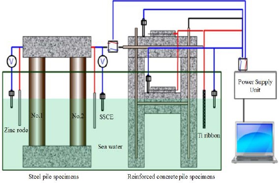
Figure 1 presents a schematic diagram of the specimens designed for leakage currents from two different types of cathodic protection systems. Zinc rods were applied to the steel pile specimens as sacrificial anodes for the SACP system, while titanium ribbons were used for the reinforced concrete pile specimens as noble anodes for the ICCP system. All electrical connections were made externally to prevent wire breakage.
2.2 Experimental Procedure
Steel pile specimens were partially submerged in a seawater tank. A 1-ohm (Ω) resistance was connected to the electrical wire linking the zinc rod and steel pile specimens. The protection current flowing from the zinc rod to the steel pile specimens was measured. Protective potential was measured using a silver-silver chloride electrode (SSCE) immersed in seawater. Both protection current and protective potential were regularly recorded using computer software. After the experiments, the recorded data were analyzed.
Reinforced concrete pile specimens were partially submerged in a seawater tank. The titanium-inserted mortar anode was created using titanium ribbons (20 mm x 160 mm x 0.5 mm) and mortar applied through grouting. The concrete mortar had a mixing ratio of 1 : 2 : 0.5 (cement : sand : fresh water), and the concrete was cured for 7 days in open air. The positive terminal of the power supply unit was connected to the titanium-inserted mortar anode, while the negative terminal was connected to the rebar of the reinforced concrete pile specimen. Direct current was supplied from the power supply unit to the reinforced concrete pile specimen. A silver-silver chloride electrode (SSCE) was used as a reference electrode to measure the protective potential. Reference electrodes were installed at various locations (upper slab, lower slab, and concrete pile) to measure protective potential under different environmental conditions. The protective potential was set at -850 mV/SSCE on the power supply unit. During the experiment, the protection current increased until it reached the set point, and both protection current and protective potential were regularly recorded using computer software.
Steel pile and reinforced concrete pile specimens were partially submerged in a seawater tank. A 1-ohm (Ω) resistance was applied between the steel pile specimens and reinforced concrete pile specimens to measure the current. Stray current generated by the two different cathodic protection systems was measured. This measurement of stray current provides essential data for developing an electric hybrid cathodic protection system that combines the SACP and ICCP systems.
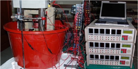
Protection current, protective potential, and 4-hour decay potential were measured to analyze cathodic protection characteristics under different systems and environmental conditions [11]. Figure 2 shows the experimental setup for steel pile and reinforced concrete pile specimens.
3. Experimental Results
3.1 Experimental Results of SACP System with Zinc Rod for Steel Pile Specimens
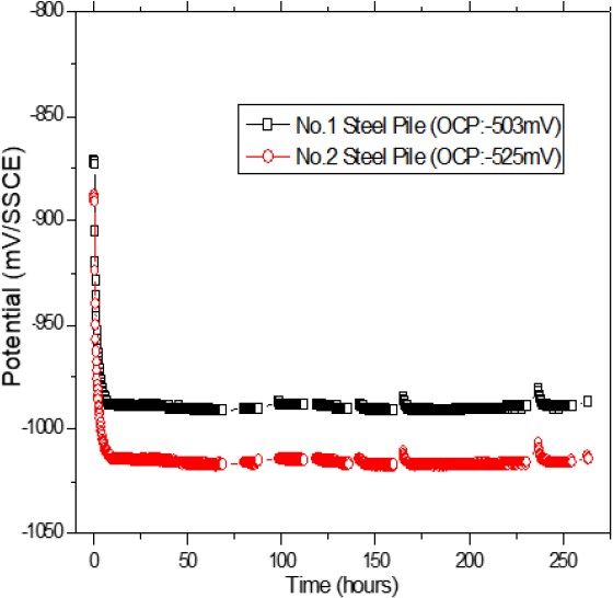
The protective potential and protection current of the steel pile specimens were measured to identify the effect of the SACP system. Figure 3 shows the change of protective potential of the steel pile specimens with time. After the zinc rod was connected to the steel pile specimens, protection current flowed. Thus, the steel pile specimens were cathodic polarized at approximately -980 to -1020 mV/SSCE. This protective potential value was maintained for approximately 270 hours.
Steel piles No. 1 and 2 were not electrically connected. In addition, because the corrosion potential values of the steel piles and sacrificial anodes used were different, there was a slight difference in the cathodic protection potential value. There was even a slight potential difference of 40 to 50 mV between the two piles, likely due to variances in half-cell potential between the zinc rod and each reference electrode. Despite these errors, the impact on the overall specimen was negligible.
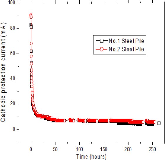
Figure 4 illustrates the change of protection current of the steel pile specimens with time. After connecting the zinc rod, a protection current of 90 mA initially flowed. Shortly thereafter, the protection current rapidly decreased to 10 mA and remained stable, which is a typical behavior of the SACP system.
3.2 Experimental Results of ICCP System with Titanium Ribbon for Reinforced Concrete Pile Specimens
The protective potential for reinforced concrete pile specimens was set at -850 mV/SSCE. The natural corrosion potentials of different parts were measured, and the results were as follows: upper slab (-108 mV/SSCE), lower slab (-164 mV/SSCE), and concrete pile (-177 mV/SSCE). The power supply unit controlled the protection current, maintaining the protective potential of the fully submerged concrete pile at -850 mV/SSCE. The protective potential of the partially submerged lower slab was measured as -790 mV/SSCE. The upper slab, exposed to the air, measured a protective potential higher than -400 mV/SSCE, which slightly increased as the atmosphere became drier. The protective potential remained lower than the natural corrosion potential by -292 mV/SSCE. Therefore, the chosen protective potential of -850 mV/SSCE for reinforced concrete pile specimens was deemed suitable for corrosion prevention.
3.3 Experimental Results of Leakage Current between SACP and ICCP Systems
The SACP system was installed for steel pile specimens, and the ICCP system was installed for reinforced concrete pile specimens, and the specimens were disconnected. The specimens were partially submerged in seawater for one month, and protection current, protective potential, and 4-hour decay potential were measured. Table 1 presents the results related to corrosion prevention. A protection current of 2.6 mA was supplied from the ICCP system’s power supply unit to maintain the protective potential at -850 mV for the concrete pile. Consequently, the protective potential of the upper and lower slabs decreased to -378 mV and -775 mV, respectively. 4-hour decay potential measurements were taken for each component: upper slab (76 mV), lower slab (201 mV), and concrete pile (258 mV). The measured value for the upper slab was lower than the recommended 100 mV threshold for corrosion prevention. The National Association of Corrosion Engineers (NACE) International SP0169-2013 states “A minimum of 100 mV of cathodic polarization between the structure and a stable reference electrode contacting the electrolyte. The formation or decay of polarization can be measured to satisfy this criterion” [12]. The concrete’s resistivity was too high in dry atmospheric conditions to supply the protection current required by the ICCP system [11].
To investigate the interference effect of the SACP system on steel pile specimens and the ICCP system on reinforced concrete pile specimens, the upper slab parts of each specimen were connected. Table 2 presents the results related to corrosion prevention when the specimens were connected. The results differed compared to when the specimens were disconnected. The protective potential of the steel pile specimens with the SACP system increased by 6–7 mV. Additionally, the 4-hour decay potential increased by 41–43 mV. Protection current increased by 3 mA for each zinc anode. However, the protective potential of the submerged reinforced concrete pile specimens was measured as -972 mV, which is lower than the set point of -850 mV. The protective potential of the lower slab decreased to -809 mV, but the protective potential of the upper slab increased to -138 mV, similar to the natural corrosion potential. The protection current of the ICCP system was 0 mA because the protective potential of the submerged concrete pile was lower than the set point. In other words, protection current flowed from the SACP system’s zinc anode to the concrete pile through seawater. An ammeter between the steel pile and reinforced concrete pile specimens measured 7 mA of stray current. In this case, output current did not flow from the ICCP system, but the protective potential of the upper slab increased until it matched the natural corrosion potential. It is worth noting that even when the SACP and ICCP systems are adjacent, unprotected areas can still remain.
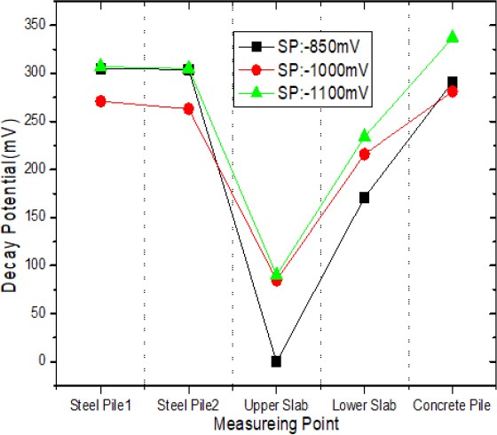
Figure 5 illustrates the decay potential of each part according to the set potential of the ICCP system. When the set potential was -850 mV, stray current flowed from the Zinc anode to the ICCP system, causing the upper slab to remain unprotected. However, when the set potential was -1000 mV, stray current did not affect the ICCP system, resulting in an increase in decay potential values for the upper slab (80 mV) and lower slab (50 mV). Conversely, the value decreased for the concrete pile submerged in seawater, decreasing by 10 mV. Stray current did not flow from the zinc anode to the concrete pile due to the lower set potential of -1000 mV. This configuration provided protection for the entire specimens without any unprotected areas. When the set potential was -1100 mV, stray current flowed from the ICCP system to the steel pile specimens, resulting in an increase of 40 mV in decay potential at the steel pile specimens. There was also a slight increase in decay potential at the reinforced concrete pile specimens.
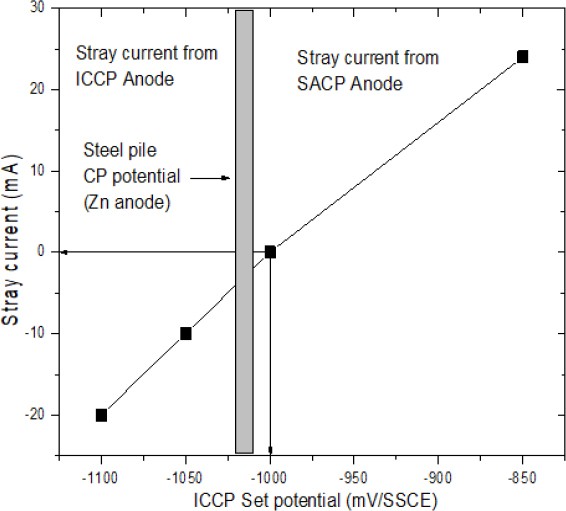
Figure 6 displays stray current levels according to the set potential of the ICCP system. Stray current varied depending on the set potential of the ICCP system. When the ICCP system’s set potential was -1000 mV, the stray current was 0 mA. For set potentials lower than -1000 mV, stray current flowed from the ICCP system to the SACP system, while for set potentials higher than -1000 mV, stray current flowed from the SACP system to the ICCP system. This result indicates that to prevent stray current when the SACP and ICCP systems are connected, an optimal set potential for the ICCP system should be around 10 to 20 mV higher than the protective potential of the SACP system.
In real structures, the protective potential can vary depending on the shape of the structure and the resistivity of concrete. To determine the optimal set potential value, simple experiments may be required for each site.
4. Conclusion
The primary goal of this study was to identify issues related to stray currents in port structures caused by the interaction of different cathodic protection systems. The following conclusions were obtained from the model experiment conducted to identify current leakage problems that may occur when a steel pile pier with the SACP system and reinforced concrete pier with the ICCP system are connected, and to find the optimal prevention conditions.
- 1. Findings for steel pile and reinforced concrete specimens in electrically disconnected state: When applying the SACP system to the steel pile specimens, the experiment yielded acceptable protection current and protective potential values throughout the three-month test period. Applying the ICCP system to reinforced concrete specimens led to acceptable protective potential values when set at -850 mV/SSCE. However, 4-hour decay potential measurements for the upper slab (76 mV) fell below the recommended 100 mV threshold for corrosion prevention according to ASTM. This is because the concrete’s resistivity was too high in dry atmospheric conditions to supply the protection current required by the ICCP system.
- 2. Observations for electrically connected steel pile and reinforced concrete specimens: Setting the ICCP system’s potential at -850 mV resulted in current leakage from the zinc anode to the reinforced concrete specimens. This caused the ICCP system’s output current to drop to 0 mA, rendering the upper slab unprotected. When the ICCP system’s potential was significantly lower than the zinc anode’s potential, current leakage occurred from the ICCP anode to the steel pile specimens. To effectively prevent stray current when connecting the SACP and ICCP systems, it is advisable to set the ICCP system’s potential around 10 to 20 mV higher than the protective potential of the SACP system.
Author Contributions
Conceptualization, D. Lee and J. Jeong; Methodology, D. Lee; Software, D. Lee; Validation, D. Lee and J. Jeong; Formal Analysis, D. Lee; Investigation, D. Lee; Resources, D. Lee; Data Curation, D. Lee; Writing—Original Draft Preparation, D. Lee; Writing—Review & Editing, J. Jeong; Visualization, D. Lee; Supervision, J. Jeong; Project Administration, J. Jeong; Funding Acquisition, J. Jeong.
References
-
S. W. Tang, Y. Yao, C. Andrade, and Z. J. Li, “Recent durability studies on concrete structure,” Cement and Concrete Research, vol. 78, Part A, pp. 143-154, 2015.
[https://doi.org/10.1016/j.cemconres.2015.05.021]

-
M. Alexander and H. Beushausen, “Durability, service life prediction, and modelling for reinforced concrete structures–review and critique,” Cement and Concrete Research, vol. 122, pp. 17-29, 2019.
[https://doi.org/10.1016/j.cemconres.2019.04.018]

-
H. V. Damme, “Concrete material science: Past, present, and future innovations,” Cement and Concrete Research, vol. 112, pp. 5-24, 2018.
[https://doi.org/10.1016/j.cemconres.2018.05.002]

-
A. Poursaee and U. M. Angst, Corrosion of Steel in Concrete Structures, 2nd Edition: Woodhead Publishing, pp. 17-34, 2023.
[https://doi.org/10.1016/B978-0-12-821840-2.00004-3]

-
M. U. Khan, S. Ahmad, and H. J. Al-Gahtani, “Chloride-induced corrosion of steel in concrete: An overview on chloride diffusion and prediction of corrosion initiation time,” Hindawi International Journal of Corrosion, vol. 2017, pp. 1-9, 2017.
[https://doi.org/10.1155/2017/5819202]

-
K. Hájková, V. Šmilauer, L. Jendele, and J. Červenka, “Prediction of reinforcement corrosion due to chloride ingress and its effects on serviceability,” Engineering Structures, vol. 174, pp. 768-777, 2018.
[https://doi.org/10.1016/j.engstruct.2018.08.006]

-
K. Takewaka, “Cathodic protection for reinforced-concrete and prestressed-concrete structures,” Corrosion Science, vol. 35, no. 5-8, pp. 1617-1623, 1993.
[https://doi.org/10.1016/0010-938X(93)90391-S]

-
A. Byrne, N. Holmes, and B. Norton, “State-of-the-art review of cathodic protection for reinforced concrete structures,” Magazine of Concrete Research, vol. 68, pp. 664-677, 2016.
[https://doi.org/10.1680/jmacr.15.00083]

-
Z. Chen, D. Koleva, and K. van Breugel, “A review on stray current-induced steel corrosion in infrastructure,” Corrosion Reviews, vol. 35, no. 6, pp. 397-423, 2017.
[https://doi.org/10.1515/corrrev-2017-0009]

-
A. O. S. Solgaard, M. Carsana, M. R. Geiker, A. Küter, and L. Bertolini, “Experimental observations of stray current effects on steel fibres embedded in mortar,” Corrosion Science, vol. 74, pp. 1-12, 2013.
[https://doi.org/10.1016/j.corsci.2013.03.014]

-
K. Hornbostel, C. K. Larsen, and M. R. Geiker, “Relationship between concrete resistivity and corrosion rate - A literature review,” Cement and Concrete Composites, vol. 39, pp. 60-72, 2013.
[https://doi.org/10.1016/j.cemconcomp.2013.03.019]

- National Association of Corrosion Engineers (NACE International), “Control of external corrosion on underground or submerged metallic piping systems,” United States of America, Oct. 04, 2013.

