Computational fluid dynamics analysis for basement ventilation in case of a fire
1Professor, Faculty of Mechanical Engineering, Ho Chi Minh City University of Technology (HCMUT), Tel: +84-08-3864-7256 (ext. 5897) ngtmtrinh@hcmut.edu.vn2Professor, Faculty of Mechanical Engineering, Ho Chi Minh City University of Technology (HCMUT), Tel: +84-08-3864-7256 (ext. 5897) nmphu@hcmut.edu.vn
3Professor, Faculty of Mechanical Engineering, Ho Chi Minh City University of Technology (HCMUT), Tel: +84-08-3864-7256 (ext. 5897) ngothientu@hcmut.edu.vn
Copyright ⓒ The Korean Society of Marine Engineering
This is an Open Access article distributed under the terms of the Creative Commons Attribution Non-Commercial License (http://creativecommons.org/licenses/by-nc/3.0), which permits unrestricted non-commercial use, distribution, and reproduction in any medium, provided the original work is properly cited.
Abstract
The basement parking lot, which provides a certain number of car spaces for users, is an effective solution for parking in crowded cities. The required ventilation system design is generally based on the number of air changes per hour, provided by local authority standards. An appropriately designed ventilation system plays an important role in ensuring a safe environment for people in case of a fire. This study aims to establish the smoke spread behavior and tenability criteria for a car fire in a basement parking lot with a small area of 2,700 m2, by using Autodesk computational fluid dynamics 2019 software. The car-fire growth rate was assumed to be a low t-squared curve. For numerical analysis, a steady-state fire was adopted at the sixth minute of the curve. The completely developed heat release rate of the car fire was 4 MW. Two common ventilation systems–a ductwork system and a combined impulse and ductwork system–were used for the simulation. The ventilation system was designed to extract 10 air changes per hour. The results suggested that the two ventilation systems guarantee a safe route for evacuation through the ramp. Besides, the ductwork ventilation system performs better at preventing the smoke from spreading, as compared to the combined ventilation system, during 6 min after ignition.
Keywords:
Basement ventilation, Computational fluid dynamics, Smoke behavior, Fire1. Introduction
The population density–especially in big cities of developing countries, including Vietnam–has been increasing rapidly in recent years. This has led to increased development of high-rise buildings including parking basements within a short time. However, this increase causes a great risk of fire and explosion due to the lack of evaluation time from design to construction, installation of fire protection work, and fire protection behavior training. As for Hanoi city, Vietnam, there are still more than 90 high-rise buildings that violate fire safety [1].
The ventilation systems of enclosed spaces, such as parking lots in a building, are designed based on their certain amount of circulation of volume per hour, through an exhaust airduct system. During the early period of construction design, most of the buildings facing problems with ventilation analysis, wind loading, or wind environment were designed using experimental tests. Recently, these tests have been effectively conducted using the computational fluid dynamics (CFD) technique [2]. CFD approaches are widely used in many industrial fields, such as steel processing for shipbuilding [3][4], solar heating-ocean thermal energy conversion [5], and food-drying [6]. In addition, over the past few years, there has been increasing interest in performing CFD analysis of smoke behavior in case of fire in enclosed spaces. Senveli et al. [7] performed an analysis and interpretation of daily emission ventilation and a fire ventilation system design in indoor eight-story parking lots of a major business center in Istanbul, using jet fans. They found that the airflow was created effectively by placing the jet fans at optimum locations. The dead zones, where no air exchanges occurred, were eliminated from the daily emission ventilation. Lu et al. [8] simulated the smoke control capacity of an impulse ventilation system in an underground car park, using a CFD simulation for 10 scenarios with a 3D model of 80 m length, 40 m width, and 3.2 m height. The fire source was defined as a car fire with a peak heat-release rate of 4 MW. The results showed that the smoke control capacity of the impulse ventilation system was sensitive to the jet fan numbers. They emphasized that a high jet fan velocity may cause severe smoke recirculation. Gao et al. [9] estimated the spread of smoke in a huge transit terminal subway station at six firesource locations, with heatrelease rates of 4 and 7.5 MW. The results showed the effects of natural and mechanical ventilation in correlation with atrium height, roof window, rate of air change, and firesource locations.
The mechanical ventilation systems for parking lots are designed based on the local standards of air change rate. Moreover, the specific structure of each parking lot is considered an important factor in the design of an efficient ventilation system. In this study, a 3D model for a small basement parking lot located in Ho Chi Minh city, Vietnam, was modeled to perform the numerical simulations in case of fire, by using the Autodesk CFD 2019 software [10]. Two common ventilation systems were used for the numerical analysis–a ductwork system and a combined impulse and ductwork system–and their operational efficiency was evaluated.
2. CFD model and methodology
The CFD domains used in this study comprised columns, internal walls, and other construction elements that could form an obstruction to the airflow, as shown in Figure 1. The total car parking area was ~2,700 m2 with 3.2 m height. Figure 1 (a) illustrates the CFD model used for the ductwork ventilation system, and Figure 1 (b) describes the combined impulse and ductwork system. The ventilation systems were designed under the basic requirements of 6 air changes per hour for general ventilation and 10 air changes per hour in the event of a fire [11].
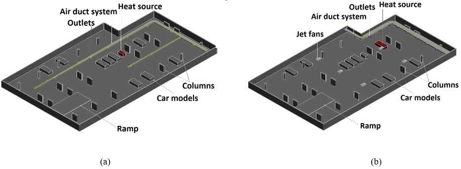
CFD model for parking lot; (a) for ductwork ventilation system, (b) combination of impulse and ductwork ventilation system
The numerical car fire source was modeled as a volumetric heat source. To model the smoke emission source, we applied a heat generation boundary condition to the entire volume and a scalar boundary condition to its upper surface. The volumetric heat source was numerically defined as a customized resistance material where the airflow could pass through with 85% free area ratio in all directions, with a conductivity of 200 W/m·K.
Based on the low t-squared fire growth rate of a car fire according to NFPA 204M [12], a steady-state design method for fire at the 6th min of the growth rate curve was assumed in this study. Thus, there were more than 5 min from ignition, for a fire alarm system to activate. The plume of hot smoky gases from the fire rose under the effect of buoyancy. When the plume hit the ceiling, it turned and then spread. As a result, it could interact with the fire sensors and make them operate. A sprinklered steady-state car fire was defined with the following parameters [13]. Heat release rate of fully developed car fire: 4 MW, convective fraction: 65%, and unit heat release: 400 kW/m2.
The air domain was subjected to a dominant forced convection airflow. The properties of the numerical air material varied with temperature at a constant pressure. The nonadiabatic walls were modeled with a film coefficient of 25 W/m2·K at a reference temperature of 27 °C.
3. Results and discussion
The steady-state solver used for the numerical simulation with Autodesk CFD 2019 was a modified PETROV-GALERKIN advection scheme. The turbulence model was SST k-ω SAS. For an incompressible flow, the thermal and scalar transport equations were solved simultaneously under the gravity effect. The scalar diffusion coefficient was 2.10–10 m2/s. No radiation model was used, and therefore, the results were evaluated through the convective fraction of fire only.
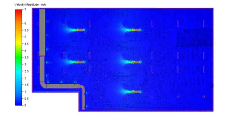
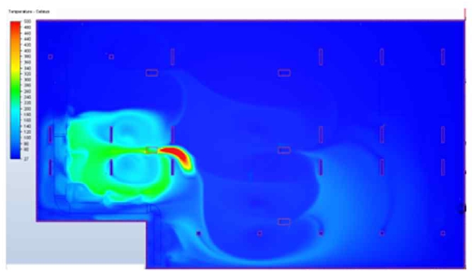
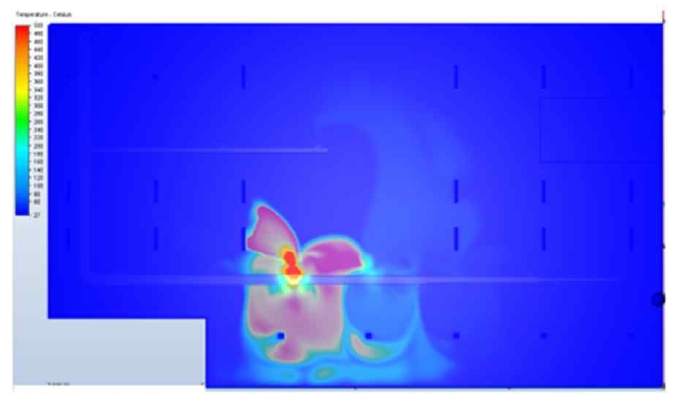
Figures 2 and 3 illustrate the velocity and temperature distribution at a cross section near the ceiling (2.7 m above the floor) of the basement parking lot.
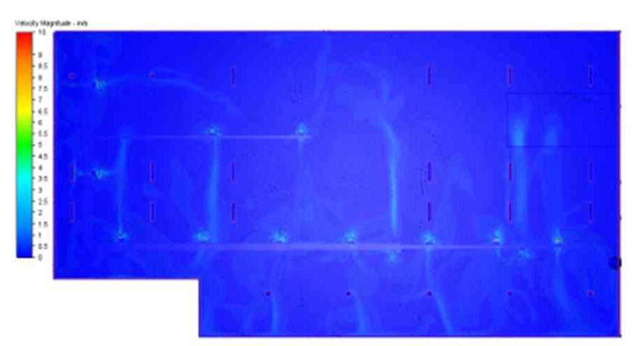
At this cross section, all air flows behind the jet fans and in front of the air-suction grille of the airduct were clearly observed. The velocity of air after it left the jet fans reached 7 m/s. As shown in Figure 2, the flow behavior met the design requirements, which ensured that the air was delivered to the ductwork system before being discharged outside. The same flow behavior could be observed for the ductwork ventilation system, as shown in Figure 5. There was not much difference in the maximum temperature near the ceiling for both systems, as shown in Figures 3 and 6.
The basic principle of smoke control systems is to limit the spread of smoke through the basement and provide a mean through which the smoke and heat can be extracted. Car-park ventilation systems were designed for the following purposes in the event of a fire: (1) To assist fire-fighters to clear smoke from a car park during and after a fire; (2) to provide a clear smoke-free access for firefighters to a point close to the location of the fire; and (3) to protect means of escape from the car park.
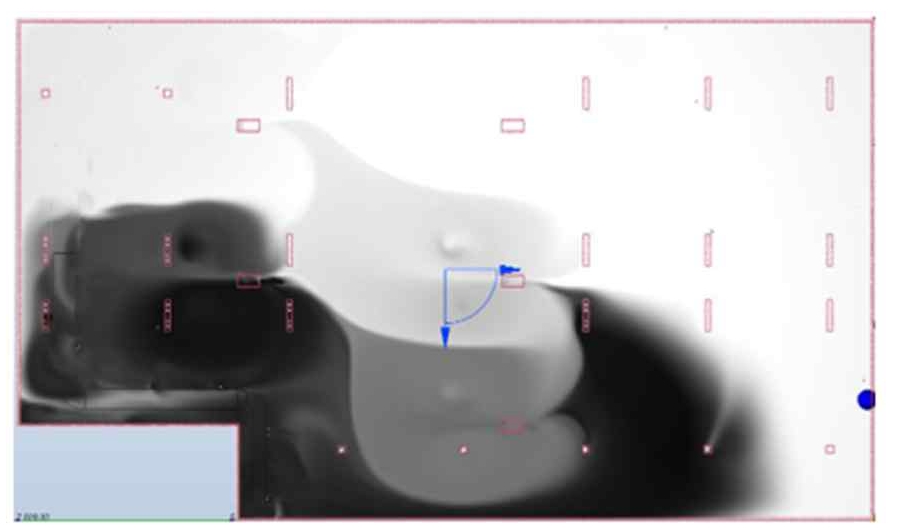
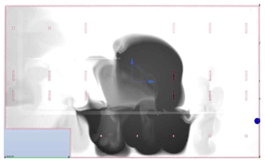
Figures 4 and 7 illustrate the smoke visibility near the ceiling for the combined impulse and ductwork system and the ductwork ventilation system, respectively. The smoke visibility capability was used to measure the distance for which a lighted sign could be observed within a smoke-filled environment. Smoke particles and irritant products could reduce the visibility. Although loss of visibility is not directly life-threatening, it can prevent or delay escape, and thus, expose people to the risk of being overtaken by fire. Both ventilation systems ensured a safe escape through the ramp. In addition, the spread of smoke for the combined ventilation system was larger than that for the ductwork system, as shown in Figures 4 and 7.
4. Conclusion
Numerical simulations of a basement parking lot with a small area of 2,700 m2 in case of fire were conducted using Autodesk CFD 2019. A steady-state method of simulating the car fire at the 6th min of the low growth rate curve was used in this study. Two common ventilation systems were used for the numerical analysis–a ductwork system and a combined impulse and ductwork system–and their operational efficiency was evaluated. The ventilation system extracted 10 air changes per hour. The effects of ventilation on the spread of smoke movement, velocity, and temperature distribution were simulated. The two ventilation systems used in our model provided a safe route for evacuation through the ramp. In addition, compared to the combined ventilation system, the ductwork ventilation system was better in reducing the spread of smoke during 6 min from ignition. The numerical simulations conducted with respect to time for 20 min for the low growth rate of a car fire will be considered in the future.
Acknowledgments
This research was funded by Ho Chi Minh City University of Technology –VNU-HCM, under grant number T-CK-2018-63.
Author Contributions
Conceptualization, H. V. Nguyen; Methodology, H. V. Nguyen and P. M. Nguyen; Software, H. V. Nguyen, P. M. Nguyen, and T. T. Ngo; Formal Analysis, H. V. Nguyen, P. M. Nguyen, T. T. Ngo, and T. T. M. Nguyen; Investigation, H. V. Nguyen, P. M. Nguyen, T. T. Ngo, and T. T. M. Nguyen; Resources, H. V. Nguyen; Data curation, H. V. Nguyen and T. T. M. Nguyen; Writing-Original Draft Preparation, H. V. Nguyen and T. T. M. Nguyen; Writing-Review & Editing, H. V. Nguyen and T. T. M. Nguyen; Visualization, H. V. Nguyen, P. M. Nguyen, and T. T. Ngo; Supervision, H. V. Nguyen; Project Administration, H. V. Nguyen; Funding Acquisition, H. V. Nguyen.
References
- Anninhthudo, https://anninhthudo.vn/chinh-tri-xa-hoi/congkhai-danh-sach-cac-cong-trinh-nha-cao-tang-ton-tai-vi-phamve-pccc/769471.antd, , 2018.
- S. M. Gomaa, E. E. Khalil, M. Fouad, and A. A. Medhat, “Ventilation system design for underground car park,” Open Journal of Technology & Engineering Disciplines (OJTED), vol. 1, no. 1, pp. 30-41, 2015.
-
T. T. Ngo, J. H. Go, T. Zhou, H. V. Nguyen, and G. S. Lee, “Enhancement of exit flow uniformity by modifying the shape of a gas torch to obtain a uniform temperature distribution on a steel plate during preheating,” Applied Sciences, vol. 8, no. 11, pp. 2197, 2018.
[https://doi.org/10.3390/app8112197]

-
T. T. Ngo, T. Zhou, J. H. Go, H. V. Nguyen, and G. S. Lee, “Improvement of the steel-plate temperature during preheating by using guide vanes to focus the flame at the outlet of a gas torch,” Energies, vol. 12, no. 5, pp. 869, 2019.
[https://doi.org/10.3390/en12050869]

-
H. V. Nguyen and G. S. Lee, “Design and analysis of a radial turbine for ocean thermal energy conversion,” Transactions of the Korean Society of Mechanical Engineers B, vol. 39, no. 3, pp. 207-214, 2015.
[https://doi.org/10.3795/KSME-B.2015.39.3.207]

-
M. P. Nguyen, T. T. Ngo, and T. D. Le, “Experimental and numerical investigation of transport phenomena and kinetics for convective shrimp drying,” Case Studies in Thermal Engineering, vol. 14, pp. 100465, 2019.
[https://doi.org/10.1016/j.csite.2019.100465]

-
A. Senveli, T. Dizman, A. Celen, D. Bilge, A. S. Dalkilic, and S. Wongwises, “CFD analysis of smoke and temperature control system of an indoor parking lot with jet fans,” Journal of Thermal Engineering, vol. 1, no. 2, pp. 116-130, 2015.
[https://doi.org/10.18186/jte.02276]

-
S. Lu, Y. H. Wang, R. F. Zhang, and H. P. Zhang, “Numerical study on impulse ventilation for smoke control in an underground car park,” Procedia Engineering, vol. 11, pp. 369–378, 2011.
[https://doi.org/10.1016/j.proeng.2011.04.671]

-
R. Gao, A. Li, X. Hao, W. Lei, and B. Deng, “Prediction of the spread of smoke in a huge transit terminal subway station under six different fire scenarios,” Tunnelling and Underground Space Technology, vol. 31, pp. 128–138, 2012.
[https://doi.org/10.1016/j.tust.2012.04.013]

- Autodesk, Inc., Autodesk Simulation CFD, 111 McInnis Parkway San Rafael, CA 94903, Available: http://usa.autodesk.com/
- L. Foluso and M. D. Nearon, “CFD application in the HVAC&R industry,” ASHRAE Journal, vol. 1, pp. 44-48, 1997.
- National Fire Protection Association (NFPA), “Guide for smoke and heat venting,” Quincy, MA, USA, NFPA 204M, 1985.
- British Standards Institution (BSI), “Components for smoke and heat control systems. Code of practice on functional recommendations and calculation methods for smoke and heat control systems for covered car parks,” British Standard BS 7346-7:2006, 2006.

