Selection of an optimizing inlet angle for the gas-liquid cylindrical cyclone separator on hydrokinetic behavior
Copyright ⓒ The Korean Society of Marine Engineering
This is an Open Access article distributed under the terms of the Creative Commons Attribution Non-Commercial License (http://creativecommons.org/licenses/by-nc/3.0), which permits unrestricted non-commercial use, distribution, and reproduction in any medium, provided the original work is properly cited.
Abstract
The Gas Liquid Cylindrical Cyclone (GLCC) separator is an attractive compact separator alternative to the conventional vessel-type separator and widely used in the petroleum industry with potential field applications. To understand the hydrokinetic properties of the flow inside GLCC body is the most important tasks for improving the performance of GLCC separator. Almost Researchers have performed CFD simulations to study the flow properties in GLCC separators in the past. This work is facing the difficulty due to the complex flow and huge dimension of GLCC. Thus, this paper focuses on studying the hydrokinetic properties of GLCC flow when inlet configuration is changed. To do this work, the inlet configuration is setup with different inclined inlet angles and different number & cross section of inlet such as single and gradually reduced inlet nozzle, dual inclined inlets nozzle. The eleven CFD models with different inclined inlet angles for both single and dual inlet GLCCs were performed to predict hydrokinetic of turbulent & swirl flow. The simulated results were compared with practical experiments in types of axial and tangential velocities. The distribution of radial, axial and tangential velocity profiles and their maximum magnitudes with respect to the change of inlet angle were carefully considered in this study. The results showed that there is excellent agreement between FEM simulations and practical experiments which allows to improve the performance of GLCC separator in industrial applications.
Keywords:
Multiphase flow, Gas liquid cylindrical cyclone (GLCC), Separator, Oil-gas, Turbulence model, Swirl1. Introduction
Crude oil production collecting from offshore field is normally being in mixture of liquid and gas forms. In order to transport them to storages, mixtures of this crude oil must be classified firstly to a unique state or every single-phase product by separators. Separating liquid and gas flow is very important in refining and gas processing applications. In petroleum industry, people have used conventional vessel-type separators which are large, heavy, and have high capital for investment and operating costs.
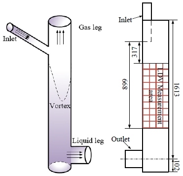
The GLCC as shown in Figure 1, is a simple, compact, low-cost separator that can be used as an economically attractive alternative to the conventional separator. The wide variety of GLCC may have different performance requirements, varying from only partial separation to a complete phase separation. Potential applications include: control for multiphase flow meters and pumps, portable well test metering, steam quality metering, flare gas scrubbing, primary surface or subsea separation and pre-separation upstream of slug catchers or primary separators [1].
The GLCC compact separator is a vertically installed pipe mounted with a mix downward inclined tangential inlet, together with a gas outlet at the top and a liquid outlet at the bottom. The two phases of the incoming mixture are separated due to the centrifugal/buoyancy forces caused by the swirling motion/vortex and the gravity forces. The liquid is forced radially towards the wall of the cylinder and is collected from the bottom, while the gas moves to the center of the cyclone and is taken out from the top. To enhance the swirling flow, the mixture of gas and liquid can be injected through two inclined tangential inlets. The flow field was measured with impact probes, a Laser Doppler Velocimeter (LDV) [3]. The axial and tangent velocity of swirling flow inside GLCC were measured in 24 locations at middle section of GLCC body.
GLCCs have been studied in different countries in the world, mostly in US by Chervron researchers. Chevron has successfully applied several GLCCs for use in low gas oil ratio (GOR) flow metering applications into petroleum industry [1][2][6][8]. But the most difficulty is how to predict exactly the separating efficiency of different flows and their behaviors inside pipe run. There are five main groups of researchers: Experimental Studies and Applications, Local Measurements, Mechanistic Modeling, Control System Studies and CFD Simulations concerning to GLCC.
Most of researchers have focused on the dependence of separating efficiency vs. flow characteristics. Chevron is the first company successfully carried out an experiment model and design a sample of GLCC [1]. In Chevron GLCC's configuration, gas and liquid streams are separated in a simple GLCC, metered by gas and liquid flow meters and recombined for transport. Several similar GLCC units were installed in place of conventional well test separators resulting in significant cost saving of equipment and site preparation.
A few researchers have built up mechanistic models of GLCC. I. Arpandi et al. [11] acquired experimental data for the GLCC at several operating pressures then measure operational envelope for liquid carryover and the equilibrium liquid level. They also developed an initial mechanistic model capable of predicting the global flow behavior in a GLCC [2][4]-[6]. Following these researches, the Tulsa University Separation Technology Projects (TUSTP) has been formed to study multiphase oil/water/gas separations. TUSTP is focused on developing mathematical models and numerical codes for the prediction of the hydrodynamic flow behavior in the GLCC and verifying these models with experimental data [4].
In Computational fluid dynamics (CFD) development, only Erdal et al. [2][3][5] presented CFD simulations utilizing a commercial code called CFX. These simulations showed details of the hydrodynamic flow behavior in the GLCC, for both single-phase and two-phase flow. Their simulation model was only specified a GLCC with inclined inlet angle at -27° as experiment model. Other CFD studies were focused on bubble trajectory analysis. Erdal [5] also measured axial and tangential velocities and turbulent intensities across the GLCC diameter at 24 different axial locations using a LDV. In their experiment, inlet water in wide range of Reynolds Numbers from 5000 to 67,000 was injected in flow rates of 10, 30 and 72 gpm for different inlet configurations. These experiment results are used to make contour plots of axial velocity, tangential velocity and turbulent kinetic energy.
Hreiz et al. [7] also studied about swirling hydrodynamics of different inlet configurations of GLCC separator via CFD simulations. They conducted many different turbulent models for GLCC based on the experimental study of Erdal. The authors showed out the high-Reynolds realizable k-epsilon model performs the best for predicting the local mean axial and tangential velocities.
How to define an optimal inclined inlet angle is a difficult problem that most of researchers need to study, especially for GLCC inlet diameters are smaller than its body diameter. In this paper, FEM simulation of eleven GLCC model with different inclined inlet angles and different number & cross section of inlet such as single and gradually reduced inlet nozzle, dual inclined inlets nozzle were performed to predict hydrokinetic of turbulent & swirl flow. The simulated results were compared with practical experiments in types of axial and tangential velocities. The distribution of radial, axial and tangential velocity profiles and their maximum magnitudes with respect to the change of inlet angle were carefully considered in this study. A majority of experimental laboratory and pilot plant studies conducted so far of flow in cyclones have covered the influence of operating parameters or changes in geometry on the separation efficiency. For examples, higher inlet velocity gives higher separation efficiency for most cyclones, but this also increases the pressure drop across the cyclone.
2. Former Experiments
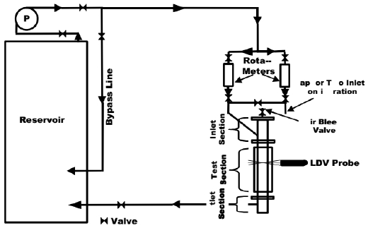
Local measurements of axial and tangential velocities and turbulence quantities are a major part of the TUSTP study. An experimental facility for single-phase flow has been designed and constructed for obtaining measurements of axial and tangential velocities and turbulence intensities below the inlet of the GLCC [3]. A schematic of the experimental facility is shown in Figure 2. The experimental facility meets following requirements.
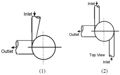
To understand the complex, turbulent, swirling flow that occurs in the GLCC and the effects of different factors (inlet geometry and fluid viscosity), a series of experiments were planned to measure local axial and tangential velocities and turbulent kinetic energy. Local measurements are conducted along the diameter at different locations below the inlet. The measurement plane is defined as the mid-plane between 12.5” to 35.4” below the inlet for two different inclined inlet configurations shown in Figure 3 with parameter as shown in Table 1.
3. CFD simulation
The effect of the gas-liquid interface on the flow field below the GLCC inlet was investigated by conducting CFD simulations of single-phase flow, utilizing a commercially available CFD code as called with FLUENT. Both simulations were carried out by using the standard high-Reynolds-number k-epsilon turbulence model. The k-epsilon turbulence model assumes that the turbulence is isotropic. However, it has been observed in the literature that turbulent swirling flow in pipes and cyclones is anisotropic. Thus, an anisotropic turbulence model should be used to predict accurately these flows. During this investigation, different turbulence models were used to study the sensitivity of the flow field predictions to the turbulence model that is utilized. Using a differential Reynolds stress turbulence model, that is an anisotropic turbulence model, simulations showed only modest improvement over the k-epsilon model prediction of the flow field in the GLCC. Therefore, for efficiency of the calculations, the k-epsilon turbulence model was used in the present two-phase flow calculations [6][8][9].
The simulated results showed in Figure 5 which presented a good agreement of between axial measured contour from Erdal’s experiments (Figure 5) [3] and simulated contour (Figure 5 (b)) for inlet configuration 1 and 2 as showed in Table 1 of this study. Color contour plots of tangential velocities are shown in Figure 6 for flow rate of 72 and 10 gpm of single gradually reduced inlet GLCC. Tangential velocity is positive on one side (left) and negative on the other side (right). This is due to the rotation of the flow. Positive velocities represent the tangential velocity out of the page and negatives represent flow into the page. Tangential velocity is high near the wall region and it decreases towards the center.
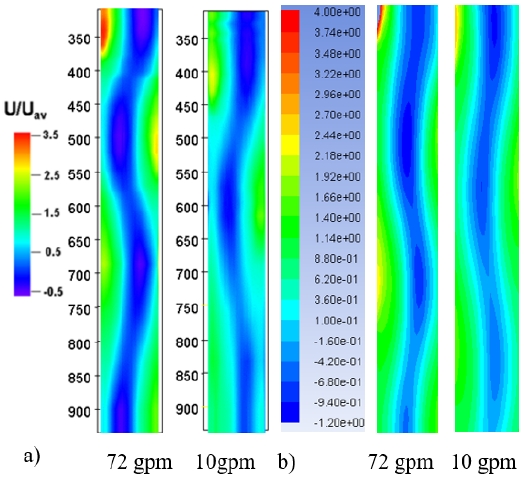
Comparison in contour of Axial Velocity between experiment (a) and the simulation (b) for Gradually Reduced Inlet
There is a decay of tangential velocity in the axial direction towards the outlet or downward axial direction. Location of zero or low tangential velocity for one incline inlet configuration has a helical (spiral) shape similar to the one observed in the axial velocity contours [7].
4. Results and Discussion
In this study, the eleven GLCC models with different inlet angles were simulated with the same meshing properties and boundary conditions as shown in Figure 4 to be sure the accuracy of the obtained results. The axial and tangential profiles are extracted from the simulated models at three sections located at x-distances below inlet section as shown in Figure 1. The model with 27° inclined inlet angle was used to validate the experimental data from Erdal’s experiments [3].
4.1 Single inclined gradually reduce inlet
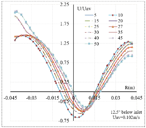
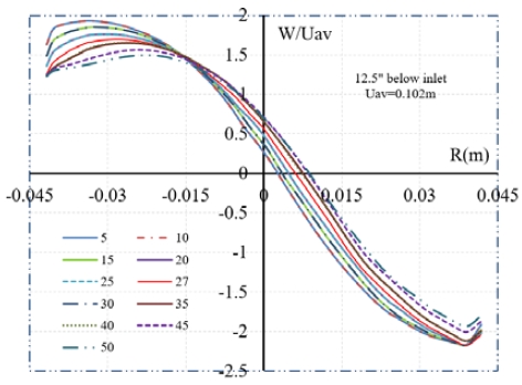
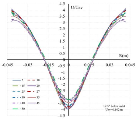
The axial velocity is an important component of the flow in GLCC body which presents the movement of fluid flow in axial direction toward the outlet. The axial velocity profile presents two flow streams (upward and downward flow) existing in GLCC body. The upward flow is near is near the cylindrical centerline directed to inlet while the downward flow near the wall directed to the bottom GLCC at narrow radial distance. Larger inlet angle creates higher magnitude of axial velocity. The axial velocity tends to reduce from the wall to near the cylindrical centerline then increase again to the wall of GLCC. Downward to bottom of GLCC, the minimum axial velocity is gradually increased its algebraic value [8].
Variation of axial velocities is slightly changed in the range of inlet angle from 5° to 30°. However, they varied significantly for inlet angles that is larger than 30°. The magnitude of axial velocities near wall region is decreased at one side and is increased in the other side while they are only increased in the region near the central axis of GLCC body according to the inclined inlet angle increase. This means that upward flow near GLCC center line is always increased when inlet inclined angle escalation. This trend of axial velocity is kept in the section near the inlet while they are reversed about GLCC centerline on the measured plans toward the bottom of GLCC.
The maximum tangential velocity depends on the inlet angle which happens mainly at the wall region. This is one of the most important factors effecting the GLCC performance. In the GLCC with high inlet angle, the tangential velocity near the wall region has slightly changed. The distribution of tangential velocity profiles with respect to different inlet angles are showed Figure 8. The maximum tangential velocity is increased significantly at the inlet angle which is larger than 35° because the fluid flow is pushed in axial direction and interacts to the upward flow which is decrease the intensity of tangential velocity.
4.2 Dual inclined inlet
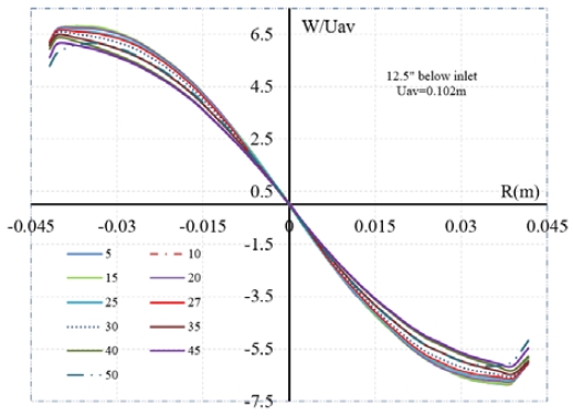
Figure 9 shows a comparison between the different simulated models. Near the inlet, the swirl decay is very low. Erdal [3] had noticed that swirl decay is more rapid for a single inlet than for two inlets which make the flow more symmetric.
Typical as the single inlet GLCC, the minimum axial velocity is almost focused at center of GLCC. Larger inlet angle creates higher magnitude of axial velocity. The axial velocity tends to reduce from the wall to near the cylindrical centerline then increase again to another wall of GLCC and axisymmetric.
Typical as the single inlet GLCC, the minimum tangential velocity is almost focused at center of GLCC. There is not much change of magnitude of tangential velocity in different inlet angles GLCC. The tangential velocity tends to reduce from the wall to near the cylindrical centerline then increase again in negative direction to another wall of GLCC and symmetric in centerline in Figure 10. Downward to bottom, the tangential velocity gradually reduced. It means that the turbulence of flow also reduced downward to bottom of GLCC.
5. Conclusion
This paper has been studied a general principal of separators and specified about GLCC models. By selecting remarkable concerned knowledge then classifying and comparison of GLCC with the conventional separators, author wishes all readers understanding these advantages.
CFD simulations were conducted to investigate the hydrokinetic of flow below the inlet of a GLCC. A suitable turbulent model in these simulations showed resulting changes when the inclined angle and nozzle configuration were varied. By comparing a proper numerical simulation results of CFD to practical experiments then these agreements showed a potential tool which can help to better understand the effect of inclined inlet angle on a complex flow patterns of the GLCC separators in both cases of single and dual inlet nozzles. The following conclusions can be extracted from this study:
- The flow patterns of tangential and axial velocities and their maximum magnitude changed insignificantly when the inclined inlet angles are varied from 5° to 30° but they increased significantly and reached to maximum value at 40° . The velocity changes of single inlet GLCC are more significant and clearly recognized than the dual inlet one.
- The axial velocities of downward flow are decreased at one side and increased in the other side. The velocities of downward flow were decayed as the flow move far from inlet downward to the outlet.
- The maximum tangential velocity depends significantly on the inlet angle which happens mainly in the wall region. The maximum tangential velocity is almost independent on the change of inlet angle at the nearest and the farthest from inlet section. The minimum tangential velocity is almost focused at center of GLCC. The maximum tangential velocity of single inlet GLCC is increased significantly at the inlet angle of 35 degree while there is not significantly changed in dual inlet one.
- Higher Reynolds flow is created a bigger change in velocity, especially for radial velocity.
Acknowledgments
This paper is an extension of the 2nd International Conference on Advanced Convergence Engineering (ICACE2019).
Author Contributions
Conceptualization, L. V. Sy; Methodology, L. V. Sy; Software, D. T. Van; Validation, D. T. Van; Formal Analysis, L. V. Sy and D. T. Van; Investigation, L. V. Sy; Resources, L. V. Sy; Data Curation, L. V. Sy; Writing—Original Draft Preparation, L. V. Sy and D. T. Van; Writing—Review & Editing, L. V. Sy; Visualization, L. V. Sy; Supervision, L. V. Sy; Project Administration, L. V. Sy; Funding Acquisition, L. V. Sy.
References
- G. E. Kouba and O. Shoham, “A review of gas-liquid cylindrical cyclone (GLCC) technology,” Proceedings of International Conference in Production Separation Systems, pp. 1-5, 1996.
-
F. M. Erdal, S. A. Shirazi, O. Shoham, and G. E. Kouba, “CFD simulation of single-phase and two-phase flow in gas-liquid cylindrical cyclone separators,” Journal of Society of Petroleum Engineers, vol. 2, no. 4, pp. 40-46, 1997.
[https://doi.org/10.2118/36645-PA]

- F. M. Erdal, “Local measurement and computational fluid dynamics simulation in GLCC Separator,” Ph.D. Thesis, The Tulsa University Separation Technology Projects, The University of Tulsa, USA, 2001.
- G. E. Kouba, “Design and performance of gas liquid cylindrical cyclone separators,” Proceedings of 7th International Conference on “Multiphase 95”, pp. 307-329, 1995.
-
F. M. Erdal and S. A. Shirazi, “Effect of inlet configuration on flow behavior in a cylindrical cyclone separator,” Proceedings of ETCE-2002 ASME Engineering Technology Conference on Energy, pp. 1-9, 2002.
[https://doi.org/10.1115/ETCE2002/MANU-29110]

-
L. V. Sy, “Influence of inlet angle on flow pattern and performance of gas liquid cylindrical cyclone separator,” The International Journal of Particulate Science and Technology, vol. 35, no. 5, pp. 555-564, 2017.
[https://doi.org/10.1080/02726351.2016.1180336]

-
R. Hreiz, R. Lainé, J. Wu, C. Lemaitre, and C. Gentric, “On the effect of the nozzle design on the performances of gas liquid cylindrical cyclone separator,” International Journal of Multiphase Flow, vol. 58, pp. 15-26, 2014.
[https://doi.org/10.1016/j.ijmultiphaseflow.2013.08.006]

-
R. Hreiz, C. Gentric, and N. Midoux, “Numerical investigation of swirling flow in cylindrical cyclones,” Chemical Engineering Research and Design, vol. 89, no. 12, pp. 2521-2539, 2011.
[https://doi.org/10.1016/j.cherd.2011.05.001]

-
K. Elsayed and C. Lacor, “The effect of cyclone inlet dimensions on the flow pattern and performance,” Applied Mathematical Modelling, vol. 35, no. 4, pp. 1952-1968, 2011.
[https://doi.org/10.1016/j.apm.2010.11.007]

-
S. Movafaghian, J. A. Marturet, R. S. Mohan, O. Shoham, and G. E. Kouba, “The effects of geometry, fluid properties and pressure on the hydrodynamics of gas– liquid cylindrical cyclone separators,” International Journal of Multiphase Flow, vol. 26, no. 6, pp. 999-1018, 2000.
[https://doi.org/10.1016/S0301-9322(99)00076-2]

-
I. Arpandi, A. R. Joshi, O. Shoham, S. Shirazi, and G. E. Kouba, “Hydrodynamics of two-phase flow in gas-liquid cylindrical cyclone separators,” Journal of Society of Petroleum Engineers, vol. 1, no. 4, pp. 427-436, 1996.
[https://doi.org/10.2118/30683-PA]


