Robust Relative Localization Using a Novel Modified Rounding Estimation Technique
Copyright © The Korean Society of Marine Engineering
This is an Open Access article distributed under the terms of the Creative Commons Attribution Non-Commercial License (http://creativecommons.org/licenses/by-nc/3.0), which permits unrestricted non-commercial use, distribution, and reproduction in any medium, provided the original work is properly cited.
Abstract
Accurate relative location estimation is a key requirement in indoor localization systems based on wireless sensor networks (WSNs). However, although these systems have applied not only various optimization algorithms but also fusion with sensors to achieve high accuracy in position determination, they are difficult to provide accurate relative azimuth and locations to users because of cumulative errors in inertial sensors with time and the influence of external magnetic fields. This paper based on ultra-wideband positioning system, which is relatively suitable for indoor localization compared to other wireless communications, presents an indoor localization system for estimating relative azimuth and location of location-unaware nodes, referred to as target nodes without applying any algorithms with complex variable and constraints to achieve high accuracy. In the proposed method, the target nodes comprising three mobile nodes estimate the relative distance and azimuth from two reference nodes that can be installed by users. In addition, in the process of estimating the relative localization information acquired from the reference nodes, positioning errors are minimized through a novel modified rounding estimation technique in which Kalman filter is applied without any time consumption algorithms. Experimental results show the feasibility and validity of the proposed system.
Keywords:
Sensor network, Wireless communication, Ultra-wideband, Two-way ranging, Kalman filter1. Introduction
In recent years, various indoor localization systems based on WSNs have received a great deal of attention in many aspects such as personnel tracking and monitoring in office environments, machine-to-machine (M2M), and indoor robot navigation [1]-[4]. Also, indoor navigation has been applied in large convention centers, which provide not only a user’s path to be traveled but also orientation and shopping information to increase user convenience [5][6]. However, because the error range of positioning in such systems is quite significant compared to the interior space, the resulting unreliable direction information is not satisfying the customers. Many of these systems use Wi-Fi [7], Zigbee [8], radio frequency identification (RFID) [9], chirp spread spectrum (CSS) [10], and ultrawideband (UWB) [11]-[16] for wireless communications plus time of arrival (ToA), time difference of arrival (TDoA), received signal strength indicator (RSSI), or angle of arrival (AoA) for range-based localization [17]-[26]. One of these wireless communications, UWB technology, can be used to track a moving target within cm level accuracy since the transmitted signal has an extremely short duration, compared to other ones.
Generally, range- based localization can estimate positioning by taking advantage of difference of received signal strength and trilateration-based positioning method. This method does not accumulate error over time; however, it can suffer errors when there are radio interference factors. Also, in the process of the development of accurate relative location estimation, these methods are integrated with several localization schemes such as convex positioning, maximum-likelihood (ML) estimation, or robust min-max optimization methods [27]-[31]. However, although theoretical and experimental results have demonstrated that these schemes are suitable for high accuracy applications, many of these iterative search techniques often require takes a great deal of time and thus are difficult to implement real time location systems (RTLSs).
More recently, to reduce iterative computation time, system architectures with micro electro mechanical systems (MEMS) sensors such as accelerometer, gyroscope, and geomagnetic sensors plus a filter for additional error compensation owing to sensor drift have been proposed [32]-[36]. Although the performance of these architectures for location estimation is suitable for RTLSs if the corresponding problem can be solved, for example, the sensitivities to electromagnetic noise attributed to a variety of electronic devices, power lines, etc. that can deteriorate its accuracy, and the position errors accumulated over time because they are calculated recursively. To solve these problems, the acquisition of azimuth and location information that is robust and stable against electromagnetic interference is required for the indoor navigation system.
Therefore, this paper based on UWB localization proposes an indoor positioning system that can resolve the cumbersome node deployment problem in WSNs and provide azimuth and positioning information to users without any MEMS sensors in which electromagnetic noises can be occurred. In the proposed method, a user with target nodes which consist of three mobile nodes can deploy two reference nodes arbitrarily in places where position recognition is required without pre-deployment of reference nodes used in trilateration, and wherein the user’s distance and azimuth can be estimated on the basis of the two reference nodes. In addition, the positioning errors are minimized by using a novel modified RE technique in which Kalman filter is applied without applying an iterative computation algorithm with complex variable and constraints.
2. Related Theories
The two-way ranging (TWR) scheme measures distance using the round-trip time of a signal, which does not require clock synchronization between the two devices. First, Device A records the starting time when a packet is transmitted, while Device B records the arrival time of the packet. Device B waits for treply followed by sending a ranging message to Device A. Here, treply is set to be longer than tpA. Finally, Device B transmits all the measured times to Device A. Here, the times are calculated using Equation (1), and the distance between two devices can then be obtained by multiplying the acquired time tpA by the speed of light c = 2.99792458 × 10⁸ m/s.
| (1) |
SDS-TWR distance measurement technology is a technological extension of TOA-based TWR technology as shown in Figure 1, whose accuracy of distance measurement can be increased by performing TWR twice. First, Device A records the packet transmission starting time while Device B stores the packet arrival time. Device B waits for treplyB followed by transmitting the ranging message to Device A. Here, treplyB is set longer than tpB. Finally, Device B transmits all the measured times to Device A. Here, the time can be calculated by Equation (2).
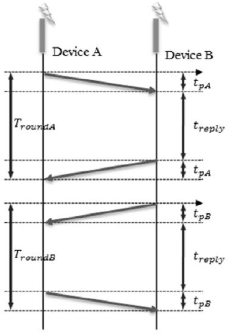
Method of distance estimation between two devices with an asynchronous system clock using symmetric double-sided two-way ranging(SDS-TWR)
| (2) |
The trilateration method measures sensor node position via angulation technique that uses the angle with the reference node or lateration one that uses distance from the reference nodes.
The lateration technique has been used widely because it can measure distance using the time of flight (TOF) of signals or signal strength without additional hardware support.
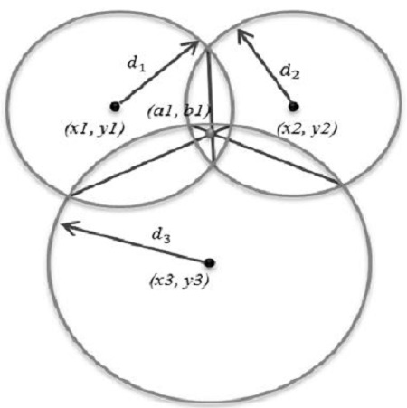
As shown in Figure 2, the coordinates of each intersection point can be determined by solving the simultaneous equations in Equation (3) if the coordinates of each reference node and distances between the mobile and reference nodes are known.
| (3) |
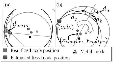
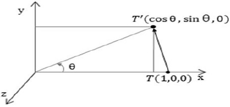
As shown in Figure 3, the rounding estimation (RE) technique [37] that we previously proposed is a method of estimating a distance based on the received distance values, similar to the trilateration method. Note that if a system using the trilateration method where three or more reference nodes are used to estimate the positions of mobile nodes is applied, position error can be generated as shown in Figure 3 (a). Thus, the RE technique is a method of estimating the position of the reference node using the intersection of a straight line through the center of the mobile node and the circle whose radius is based on the received distance value between the reference and mobile nodes as shown in Figure 3 (b). Figure 4 shows the transformation of the rotation of coordinates. When P1(1,0,0) is rotated by an angle θ around the z axis, it is transformed into x = cos θ , y = sin θ, z = 0 while P2(0,1,0) is rotated by an angle θ, it is transformed into x = cos(θ + π/2), y = sin(θ + π/2) , z = 0 that is x = -sin θ, y = cos θ, z = 0 according to the basic equation of trigonometric functions. For P3(0,0,1) which is a rotating axis, x = 0, y = 0, z = 1 is maintained as the same. The points are represented as a columnbased matrix as follows:
| (4) |
which is a z-axis-based matrix value among the Euler angle transformations.
3. Produced Method Using a Modified Re Technique
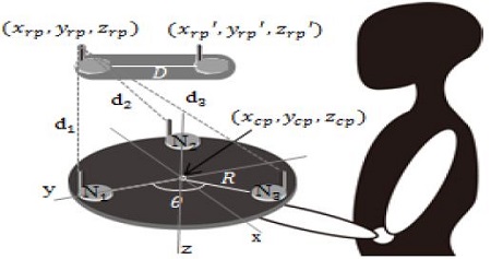
Here we discuss the theoretical background of the proposed method. The proposed system consists of two reference nodes and target nodes comprising three mobile nodes which are held in the user’s hand as shown in Figure 5. Let the target nodes be deployed at intervals of 120° at a constant radius to estimate azimuth and the reference nodes be deployed in a straight line at an appropriate distance. Assuming that zrp, zrp′, and zcp are all the same value, the three mobile nodes can be deployed according to Equation (5).
| (5) |
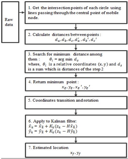
where R refers to the distance to each node from the center of the mobile nodes deployed in a triangular arrangement, and θ = 2π(k - 1)/3 refers to the angle of the angle of the kth node deployed. Figure 6 shows a block diagram of the proposed localization method using a modified RE technique in which Kalman filter is applied, not the trilateration technique to take advantage of the existing Monge’s theorem. This method is divided largely into estimation of the reference node and estimation of the relative coordinate. In the first step of reference node estimation, the coordinates of the reference nodes are estimated on the basis of the mobile nodes in the order of (a), (b), and (c) in Figure 7. First, acquire the coordinates of the intersection points between each circle formed using received distance values between the mobile and reference nodes dn1, dn2, and dn3 and a straight line with a slope calculated by Equation (6) passing through the central point of the mobile nodes, which are deployed around a constant radius in a triangular arrangement, as shown in Figure 7 (a).
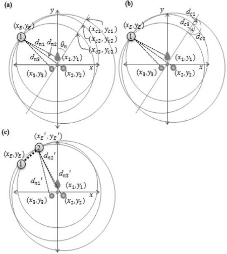
Estimating stage of the reference node: (a) get the intersection point of circle and line, (b) get the first node coordinates, and (c) get the second node coordinates by repeating previous two processes.
| (6) |
where θz is a slope of a straight line and n = 0, 1, 2, ..., 179.
Next, calculate distances between the intersections of the straight line and the circles determined for each slope using Equation (7) as shown in Figure 7 (a).
| (7) |
where, dci is distance of each intersection point, and (xcv, yci), (xcj, ycj) are intersection points. As shown in Figure 7 (b), find the minimum sum of distances (dc1, dc2, and dc3) between the intersections of the acquired circles and the straight line. Here, if more than two places with the minimum distance can be acquired, the final position of the reference node can be estimated via the average of the coordinates according to probability. In Figure 7 (c), a coordinate of (xE′, yE′) which is kept at a constant distance, is estimated using the same estimation method used for a coordinate of xE, yE. The second step of relative coordinate estimation follows the order of (a), (b), (c), and (d) in Figure 8. The coordinate of the reference node estimated via the coordinate transformation and that of the actual reference node are kept the same to acquire the final relative coordinate of the mobile node. As shown in Figure 8 (a), the longer the distance to the reference node is, the higher the error is, which decreases the reliability of the reference point of the coordinate transformation. Therefore, the reference point for the coordinate transformation is selected as the smaller value of d1 and d2. As shown in Figure 8 (b), (xE, yE) is transformed by as much as Δx and Δy obtained by Equation (8) to keep them the same with the reference point (xR, yR) for coordinate transformation of the mobile node.
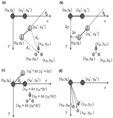
Estimating stage of relative coordinates: (a) compare with the distance from the mobile node to reference nodes 1 and 2, (b) transform the coordinates based on estimated reference node, (c) get the azimuth of the mobile node, and (d) get the final coordinates of mobile node.
| (8) |
In Figure 8 (c), (xE′, yE′) and (xR′, yR′) are kept the same to acquire the final azimuth θg of the mobile node for rotational transformation of the mobile node. In Figure 8 (d), based on the acquired azimuth, the mobile node is rotated for transformation using Equation (9) and Equation (10) to obtain the coordinate of the mobile node determined based on the reference node.
| (9) |
| (10) |
where xkt, ykt, and zkt refer to the coordinates of the mobile node prior to the rotation transformation, while xrt, yrt, and zrt refer to the coordinates of the mobile node after rotation transformation. In addition, xf, yf, and zf refer to the finally determined coordinates of the mobile node.
4. Experiment and Analysis
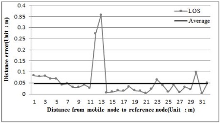
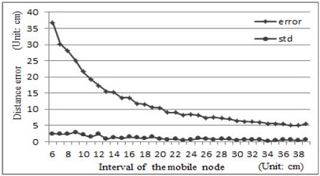
Experiments are performed by a prototype made from the proposed system consisting of the 3 mobile nodes and the 2 reference nodes. The radius (R) for node deployment of the mobile nodes was determined by computer simulation. Before that, in order to validate the measurement distance error of the P410RCM module, measurement results obtained by keeping a distance between the reference and mobile nodes of 1–31 m at 1-m intervals are shown in Figure 9. The experiment result showed that the standard deviation of the distances was 7 cm, and average distance error was 4.6 cm. Here, we found that errors abruptly increased at 12 m and 13 m, which was due to an obstacle in the experimental environment that blocked the line of sight (LOS). Other than those areas, no unexpected result was found. Currently, various studies for improving accuracy under the NLOS condition have been conducted; however, in the present study, we considered only the LOS condition. Figure 10 shows a graph of the computer simulation result. The x axis represents the radius (R) of the node deployment gap between the mobile nodes, while the y axis represents the distance error of the reference nodes for each node. The simulation was conducted while increasing the radius from 6 cm to 38 cm. For each radius, an average value of the results obtained by rotating the mobile nodes from 0° to 360° was used. The simulation result revealed that when the radius for the initial deployment was 6 cm, the estimated distance error of the reference node was about 36.7 cm, which was higher relative to the intrinsic error of the UWB module. Furthermore, as the radius of the mobile node increased, the distance error of the reference node decreased continuously to converge to about 5.4 cm at a radius of 35 cm.
5. Conclusions and Future Research Directions
This paper describes a novel modified RE technique that the positioning errors can be minimized and an indoor localization system for acquiring a user’s azimuth and location information based on two reference nodes and target nodes, which are robust against position errors due to the effects of external magnetic fields and cumulative errors caused by using MEMS sensor fusion systems. In addition, the proposed system in an indoor environment can estimate its own relative azimuth and position without pre-deployment of the reference nodes which are used in conventional tri- or multilateration and be minimized the positioning errors by using a novel modified RE technique in which Kalman filter is applied without applying an iterative search techniques that require computation time by using complex variable and constraints. To verify the validity of our proposed scheme, the robustness against cumulative errors over time and magnetic field was numerically analyzed through the actual prototype experiments. In our future research, we will extend the localization of LOS environment to that of NLOS environment. The performance of a fast-moving sensor network and three-dimensional nodes will be studied theoretically and experimentally.
Acknowledgments
This research was supported by Basic Science Research Program through the National Research Foundation of Korea(NRF) funded by the Ministry of Education (No. 2014R1A1A4A01008081)
This paper is extended and updated from the short version that appeared in the Proceedings of the International Symposium on Marine Engineering and Technology (ISMT 2014), held at BEXCO, Busan, Korea on October 17-19, 2014.
References
-
I. F. Akyildiz, W. Su, Y. Sankarasubramaniam, and E. Cayirci, “Wireless sensor networks: A survey,”, Computer Networks, 38(4), p393-422, (2002).
[https://doi.org/10.1016/S1389-1286(01)00302-4]

-
L. Zhang, Q. Cheng, Y. Wang, and S. Zeadally, “A novel distributed sensor positioning system using the dual of target tracking,”, IEEE Transaction on Computers, 57(2), p246-260, (2008).
[https://doi.org/10.1109/TC.2007.70792]

-
H. Alemdar, and C. Ersoy, “Wireless sensor networks for healthcare : A survey,”, Computer Networks, 54(15), p2688-2710, (2010).
[https://doi.org/10.1016/j.comnet.2010.05.003]

-
E. L. van den Broek, “Ubiquitous emotion-aware computing,”, Personal and Ubiquitous Computing, 17(1), p53-67, (2013).
[https://doi.org/10.1007/s00779-011-0479-9]

- http://www.webpronews.com/ces-2012-google-mapsindoors-of-las-vegas-hotels-2012-01, Accessed August 20, 2012.
-
P. Mirowski, P. Whiting, H. Steck, R. Palaniappan, M. MacDonald, D. Hartmann, and T. K. Ho, “Probability kernel regression for WiFi localisation,”, Journal of Location Based Services, 6(2), p81-100, (2012).
[https://doi.org/10.1080/17489725.2012.694723]

-
L. Chen, B. Li, K. Zhao, C. Rizos, and Z. Zheng, “An Improved Algorithm to Generate a Wi-Fi Fingerprint Database for Indoor Positioning,”, Sensors, 13(8), p11085-11096, (2013).
[https://doi.org/10.3390/s130811085]

- http://www.ZigBee.org/en/about/faq.asp, Accessed December 10, 2011.
-
C. H. Oh, “Location estimation using space time signal processing in RFID wireless sensor networks,”, International Journal of Distributed Sensor Networks, 2013, Article ID 634531, p8, (2013).
[https://doi.org/10.1155/2013/634531]

-
J. Wang, Q. Gao, Y. Yu, H. Wang, and M. Jin, “Toward robust indoor localization based on bayesian filter using chirp-spread-spectrum ranging,”, IEEE Transactions on Industrial Electronics, 59(3), p1622-1629, (2012).
[https://doi.org/10.1109/TIE.2011.2165462]

-
X. Shen, M. Guizani, R. C. Qiu, and T. Le-Ngoc, Ultra-Wideband Wireless Communications and Networks, John Wiley, (2006).
[https://doi.org/10.1002/0470028521]

-
M. Mahfouz, C. Zhang, B. Merkl, M. Kuhn, and A. E. Fathy, “Investigation of high-accuracy indoor 3-D positioning using UWB technology,”, IEEE transaction on Microwave Theory and Technology, 56(6), p1316-1330, (2008).
[https://doi.org/10.1109/TMTT.2008.923351]

-
Z. Zhang, H. Li, D. Yang, and C. Pei, “Collaborative compressed spectrum sensing : What if spectrum is not sparse?,”, IEEE Electronics Letters, 47(8), p519-520, (2011).
[https://doi.org/10.1049/el.2011.0274]

-
D. Yang, H. Li, Z. Zhang, and G.D. Peterson, “Compressive sensing based sub-mm accuracy UWB positioning systems : A spaceCtime approach,”, Digital Signal Processing, 23(1), p340-354, (2012).
[https://doi.org/10.1016/j.dsp.2012.07.012]

-
G. Garcia, L. Muppirisetty, and H. Wymeersch, “On the trade-off between accuracy and delay in UWB navigation,”, IEEE Communications Letters, 17(1), p39-42, (2013).
[https://doi.org/10.1109/LCOMM.2012.120312.121542]

-
H. Jiang, C. Liu, Y. Zhang, and H. Cui, “Fast 3D node localization in multipath for UWB wireless sensor networks using modified propagator method,”, International Journal of Distributed Sensor Networks, 2014, Article ID 312535, p8, (2014).
[https://doi.org/10.1155/2014/312535]

-
X. Liu, G. Zhao, and X. Ma, “Target localization and tracking in noisy binary sensor networks with known spatial topology,”, Wireless Communications and Mobile Computing, 9(8), p1028-1039, (2009).
[https://doi.org/10.1002/wcm.652]

-
M. P.Michaelides, and C. G. Panayiotou, “SNAP : fault tolerant event location estimation in sensor networks using binary data,”, IEEE Transactions on Computers, 58(9), p1185-1197, (2009).
[https://doi.org/10.1109/TC.2009.60]

-
E. Mas¸azade, R. Niu, P. K. Varshney, and M. Keskinoz, “Energy aware iterative source localization for wireless sensor networks,”, IEEE Transactions on Signal Processing, 58(9), p4824-4835, (2010).
[https://doi.org/10.1109/TSP.2010.2051433]

-
W. Meng, W. Xiao, and L. Xie, “An efficient EM algorithm for energy-based multisource localization in wireless sensor networks,”, IEEE Transactions on Instrumentation and Measurement, 60(3), p1017-1027, (2011).
[https://doi.org/10.1109/TIM.2010.2047035]

-
L. Cheng, C. D. Wu, Y. Z. Zhang, and Y. Wang, “Indoor robot localization based on wireless sensor networks,”, IEEE Transactions on Consumer Electronics, 57(3), p1099-1104, (2011).
[https://doi.org/10.1109/TCE.2011.6018861]

-
S. W. Lee, D. Y. Lee, and C. W. Lee, “Enhanced DV-Hop algorithm with reduced hop-size error in ad hoc networks,”, IEICE Transactions on Communications, 94(7), p2130-2132, (2011).
[https://doi.org/10.1587/transcom.E94.B.2130]

-
J. Lee, W. Chung, and E. Kim, “A new range-free localization method using quadratic programming,”, Computer Communications, 34(8), p998-1010, (2011).
[https://doi.org/10.1016/j.comcom.2010.10.013]

-
Z. Zhong, and T. He, “RSD : A metric for achieving rangefree localization beyond connectivity,”, IEEE Transactions on Parallel and Distributed Systems, 22(11), p1943-1951, (2011).
[https://doi.org/10.1109/TPDS.2011.105]

- K. Lu, X. Xiang, D. Zhang, R. Mao, and Y. Feng, “Localization algorithm based on maximum a posteriori in wireless sensor networks,”, International Journal of Distributed Sensor Networks, 2012, Article ID 260302, p7, (2012).
-
L. Cheng, C. Wu, Y. Zhang, H. Wu, M. Li, and C. Maple, “A survey of localization in wireless sensor network,”, International Journal of Distributed Sensor Networks, 2012, Article ID 962523, p12, (2012).
[https://doi.org/10.1155/2012/962523]

-
P. Biswas, T.C. Liang, K. C. Toh, Y. Ye, and T. C. Wang, “Semidefinite Programming Approaches for Sensor Network Localization with Noisy Distance Measurements,”, IEEE Transactions on Automation Science and Engineering, 3(4), p360-371, (2006).
[https://doi.org/10.1109/TASE.2006.877401]

-
P. Tseng, “Second-order cone programming relaxation of sensor network localization,”, SIAM Journal on Optimization, 18(1), p156-185, (2007).
[https://doi.org/10.1137/050640308]

-
K. Yang, G. Wang, and Z.-Q. Luo, “Efficient convex relaxation methods for robust target localization by a sensor network using time differences of arrivals,”, IEEE Transactions on Signal Processing, 57(7), p2775-2784, (2009).
[https://doi.org/10.1109/TSP.2009.2016891]

-
Y. Noam, and H. Messer, “Notes on the tightness of the hybrid cramer-rao lower bound,”, IEEE Transaction on Signal Processing, 57(6), p2074-2084, (2009).
[https://doi.org/10.1109/TSP.2009.2015113]

-
W. Y. Chiu, B. S. Chen, and C. Y. Yang, “Robust relative location estimation in wireless sensor networks with inexact position problems,”, IEEE Transactions on Mobile Computing, 11(6), p935-946, (2012).
[https://doi.org/10.1109/TMC.2011.111]

-
Y. Chon, and H. Cha, "LifeMap : A smartphone-based context provider for location-based services,”, IEEE Pervasive Computing, 10(2), p58-67, (2011).
[https://doi.org/10.1109/MPRV.2011.13]

-
B. G. Lee, and W. Y. Chung, “Multitarget threedimensional indoor navigation on a PDA in a wireless sensor network,”, IEEE Sensors Journal, 11(3), p799-807, (2011).
[https://doi.org/10.1109/JSEN.2010.2076802]

-
A. R. J. Ruiz, F. S. Granja, J. C. Prieto Honorate, and J. I. G. Rosas, “Accurate pedestrian indoor navigation by tightly coupling foot-mounted IMU and RFID measurements,”, IEEE Transaction on Instrument and Measurement, 61(1), p178-189, (2012).
[https://doi.org/10.1109/TIM.2011.2159317]

-
R. Zhang, F. Hoflinger, and L. Reindl, “Inertial sensor based indoor localization and monitoring system for emergency responders,”, IEEE Sensors Journal, 13(2), p838-848, (2013).
[https://doi.org/10.1109/JSEN.2012.2227593]

- H. J. Cho, Y. S. Ha, J. H. Kim, K. S. Ryu, and D. H. Seo, “Convergence localization system for self-localization based on estimation of relative coordinates,”, International Symposium on Marine Engineering & Technology, p80-83, (2013).
-
H. J. Cho, J. S. Kim, S. G. Lee, J. W. Kim, and H. Seo, “Fixed node reduction technique using relative coordinate estimation algorithm,”, Journal of the Korean Society of Marine Engineering, 37(2), p220-226, (2013).
[https://doi.org/10.5916/jkosme.2013.37.2.220]


